436 Keysight NFA Series Noise Figure Analyzers Service Guide
Assembly Replacement Procedures
A5 Solid State Drive
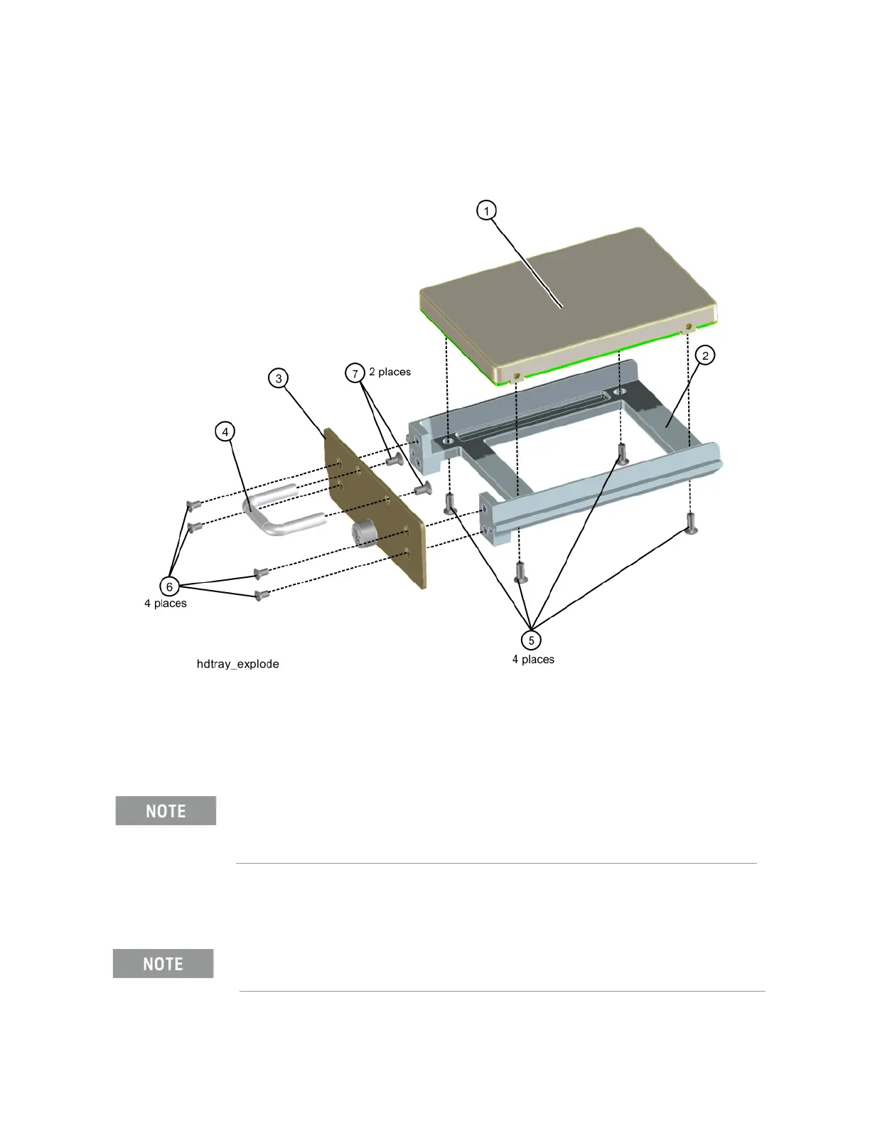
2. Refer to Figure 15-36. Remove the four screws (5) (0515-1035) from the
disk drive tray that secure the SSD (1).
Figure 15-36 Disk Drive Tray Screws
Replacement
1. Refer to Figure 15-36. Place the new SSD into the tray assembly and
attach with the four screws (5) (0515-1035). Torque to 9 inch-pounds.
2. Refer to Figure 15-35. Slide the SSD into the CPU assembly and push to
mate the connector. Secure the thumb screw to 9 inch-pounds.
Make sure not to use the 0515-0372 screw because for the PC6 processor
it will cause the SSD to interfere with the CPU memory card.
Refer to Chapter 16, “Post-Repair Procedures.” and perform all of the
specified tasks for replacing the A5 Disk Drive assembly.