Fig.4-4 Wiring of analog output
Notes:
1. When using analog input, a filter capacitor common mode inductor can be installed between signal input
and GND
2. The analog input voltage is better under 15V.
3. Analog input and output signals are easily disturbed by noise, so shielded cables must be used to transmit
these signals and the cable length should be as short as possible.
4. The analog output terminal can stand the voltage under 15V
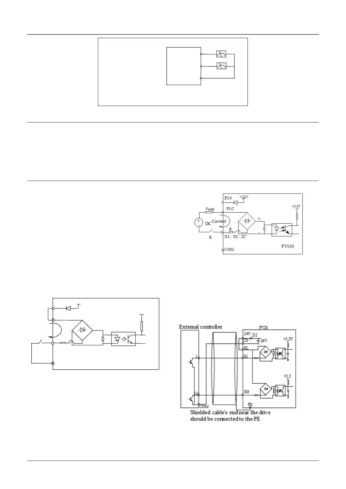
Wiring of multiple function input terminal and
operation terminal
FV20 multi-function input terminal uses a full-bridge
rectifying circuit as shown in Fig.4-7. PLC is the
common terminal of terminals X1~X6, The current
flows through terminal PLC can be pulling current
and the feeding current. Wiring of X1~X6 is flexible
and the typical wiring are as follows:
1. Dry contacts method
1) Use the internal 24V power supply of VFD, the
wiring is as in fig.4-7.
Fig.4-7 Wiring method of using the internal 24V power
supply
2) Use external power supply, (The power supply
must satisfy the UL CLASS 2 standard and a 4A
fuse must be added between the power supply and
terminal), the wiring is as Fig.4-8 (Make sure the
PLC and 24V terminal is disconnected)
Fig.4-8 Wiring of external power supply
2. Source/drain connection method
1) Use internal +24V power supply of VFD and the
external controller uses NPN transistors whose
common emitter are connected, as shown in the
fig.4-9’’
Fig.4-9 Use internal power supply
for Source connection

 Loading...
