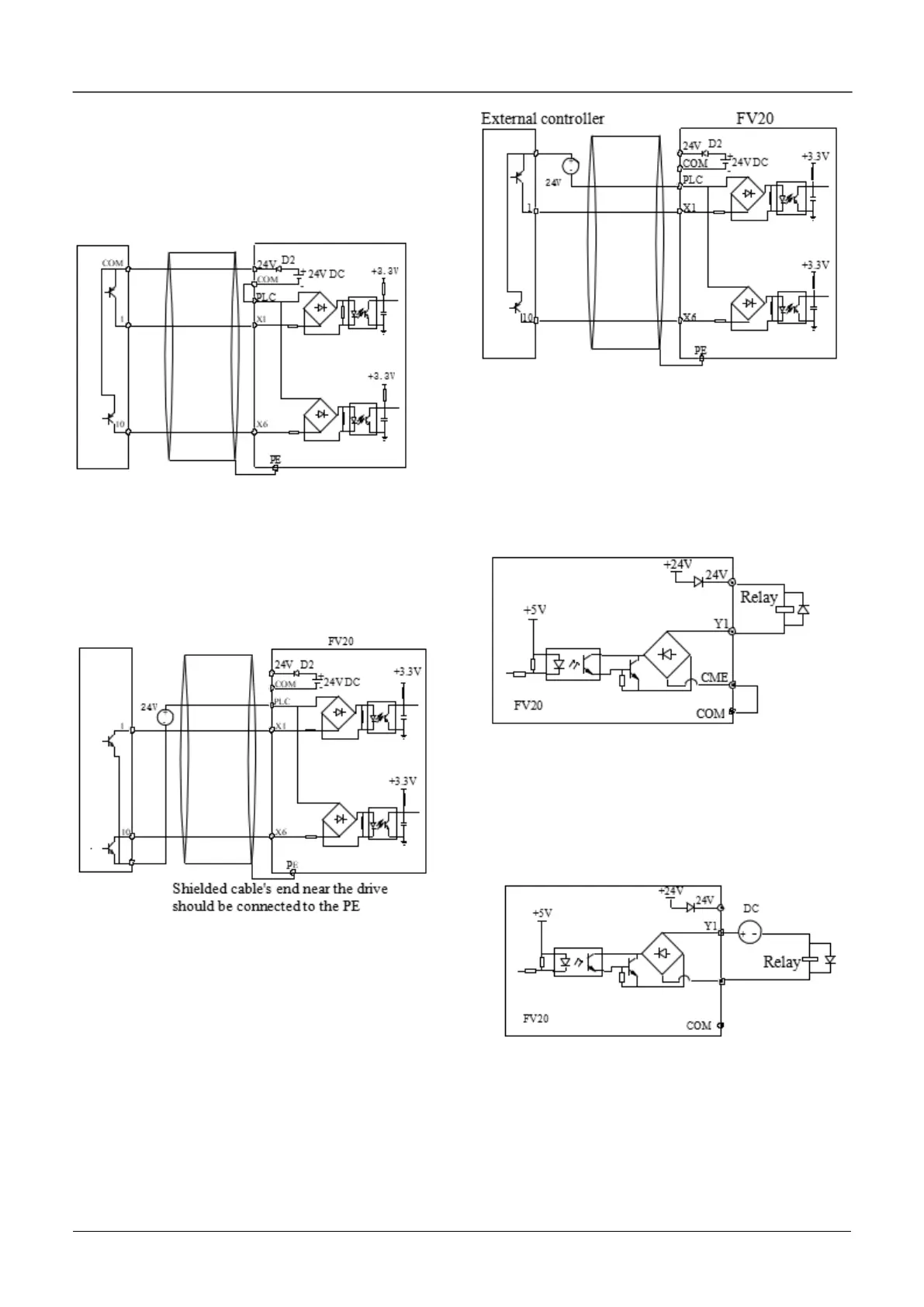
2) Use internal +24V power supply and the external
controller uses PNP transistors whose common
emitter are connected, as shown in the fig
4-10(Make sure the PLC and 24V terminal is
disconnected). The wiring is as shown in fig.4-10
Fig 4-10 Use internal power supply
for drain connection
3) Use external power supply for source connection
(Make sure the PLC and 24V terminal is
disconnected). As shown in the fig.4-11
Fig 4-11 Use external power supply
for source connection
4) Use external power supply for drain connection
(Make sure the PLC and 24V terminal is
disconnected). As shown in the fig 4-12
Fig 4-12 Use external power supply
for drain connection
Multi-function output terminal wiring
1. Multi-function output terminal Y1 can use the
internal 24 power supply, the wiring is as shown in
Fig.4-13
Fig 4-13 Wiring method 1 of multi-function
output terminal Y1
2. Multi-function output terminal Y1can use the
external 24 power supply too, the wiring is as shown
in Fig.4-14.
Fig 4-14 Wiring method 2 of multi-function
output terminal Y1
3. Y1 can also be used as pulse frequency output, If
Y2 uses the internal 24V power supply. The wiring
is shown in Fig.4-15.
 Loading...

