DOCUMENT 301900, REVISION D
18 EPISENSOR USER GUIDE
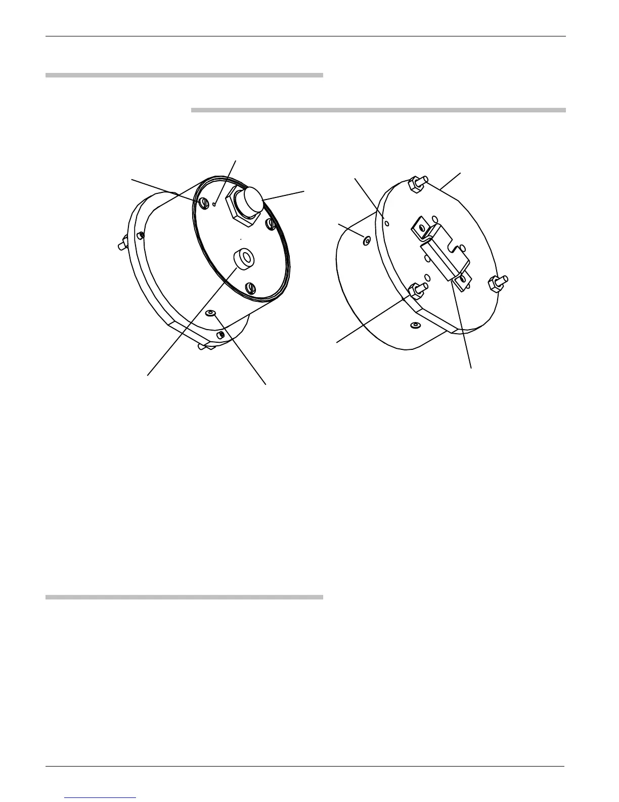
EpiSensor External Features
Figure 9: The EpiSensor.
Electrical connector
Leveling bubble
X sensor adjustment access hole
One of three screws
securing EpiSensor case
Z sensor adjustment access hole
Mounting bracket
One of three leveling feet
Y sensor
adjustment hole
Flat edge of case -- aligns with
Y north/south sensor axis
Grounding screw
The EpiSensor's anodized-aluminum exterior has:
! An O-ring-sealed cover to prevent moisture and dirt from entering
the instrument
! Three access holes (covered by seal screws) through which the zero
offset of the X, Y and Z sensors may be adjusted
! Three adjustable leveling feet
! A connector for the analog output voltages from the accelerometers
and for supplying power and control signals to the EpiSensor
! A bubble level for leveling the unit
! External mounting bracket
Required Power
If you are using the EpiSensor with a Kinemetrics Altus instrument, the
+/-12V power will be supplied from the recorder.
If you are using a Kinemetrics recorder with the EpiSensor configured to
use the low-noise option, read the appropriate section in Chapter 6 to be
sure your Altus instrument can provide sufficient current for the EpiSensor.
 Loading...