DOCUMENT 301900, REVISION D
EPISENSOR USER GUIDE 35
5. Reference
Theory of Operation
The EpiSensor consists of three orthogonally mounted force balance
accelerometers (FBAs) – X-axis, Y-axis and Z-axis – inside a sensor casing.
Each accelerometer module is identical and plugs into a board that provides
the final output circuit and the carrier oscillator.
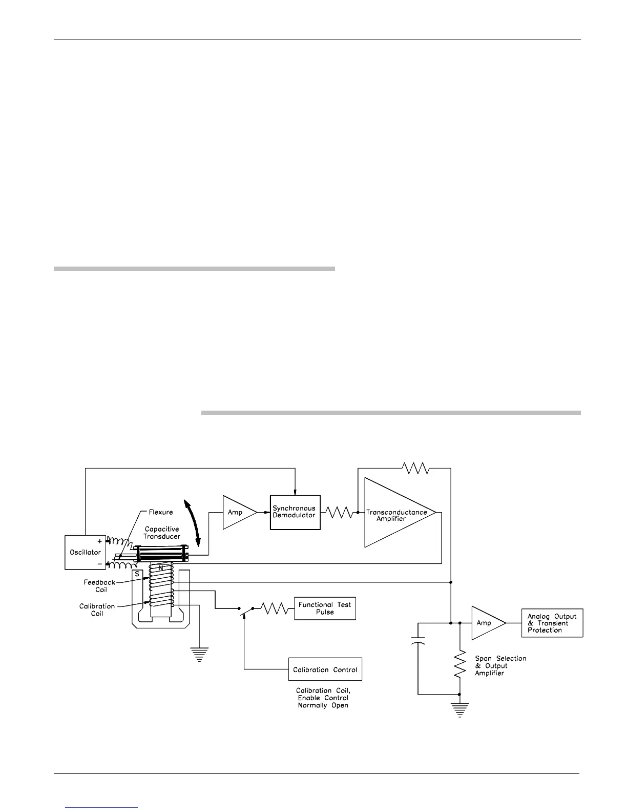
The figure below shows a simplified block diagram of the major
components of each of the FBAs.
Figure 18: Simplified block diagram of an accelerometer
 Loading...