DOCUMENT 301900, REVISION D
42 EPISENSOR USER GUIDE
Electrical Interface
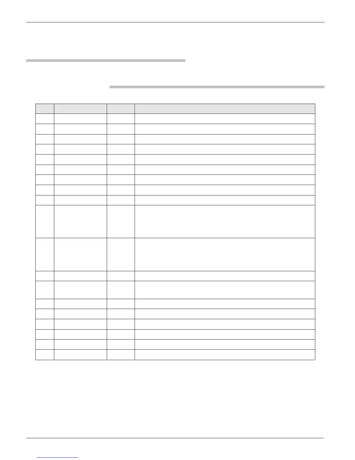
Table 8: Input connections
Pin Name I/O Description
L X + signal Output + X axis signal output
M X – signal Output – X axis signal output
N X shield X shield
A Y + signal Output + Y axis signal output
B Y – signal Output – Y axis signal output
P Y shield Y shield
C Z + signal Output + Z axis signal output
D Z – signal Output – Z axis signal output
R Z shield Z shield
E Cal Input Calibration input to excite the calibration coils of all three sensors.
Only active when calibration coil enable (CCE) is active.
A voltage of 2.5V will produce a nominal output equivalent
to an input of .125g.
F CCE Input Calibration coil enable. Normally the CCE must be disconnected or
set at a voltage below 0.5 volts. To enable the calibration coil apply
a signal of +5 to +12 volts to this pin. Can be driven to –12 volts in
the disable state.
J + 12 V Input +12 VDC power input.
H – 12 V Input – 12 VDC power input. (Leave disconnected when running with
+12V single power supply option)
K Power common Input Power connection
U PGP ground Instrument case ground
G Ground
S Ground
T Ground
V Ground
 Loading...