DOCUMENT 301900, REVISION D
60 EPISENSOR USER GUIDE
4. Once the wires have been run through the correct holes in the
grommet, strip 1/8" off the wire tips, then solder tin them as shown
in Figure 31.
Figure 31: Foil tape and stripped-and-tinned wires
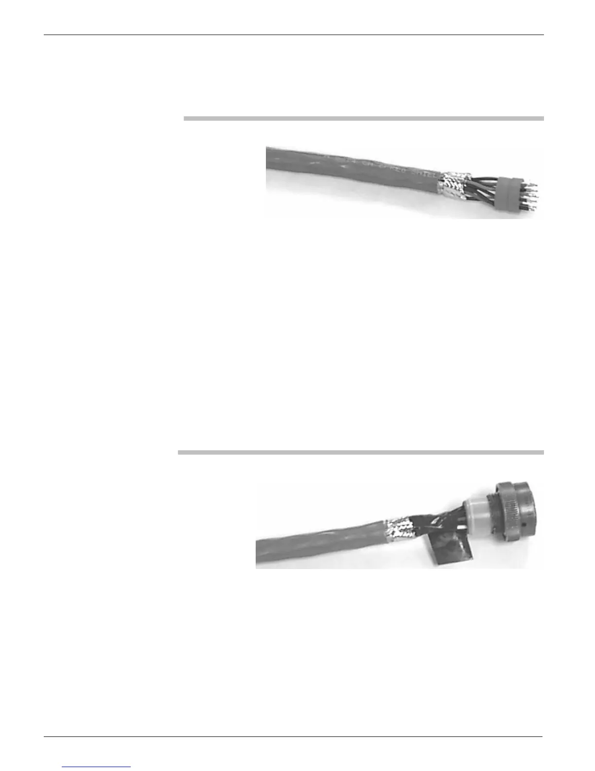
Final Assembly of the Recorder End
To complete the final assembly of the recorder end of the cable, solder the
wires into the recorder mating connector:
1. Start at the bottom and work toward the top (pin A marks the top),
soldering the wires into the connector.
Note: When cool, the soldered joints should have a smooth, shiny
surface. Use enough solder to just fill the connector cup.
2. When done with the soldering, slide the grommet and plastic
grommet ring forward and up against the connector head (shown
on the right side of Figure 32).
3. Then apply two turns of insulating PVC tape between the back of
the grommet and the foil tape (also shown in Figure 32).
Figure 32: Wrapping the connection with PVC tape
Tightly wrap 1" x 3" foil tape around the cable between the back of
grommet and end of the cable outer jacket, as shown in Figure 33.
Note: The foil tape must be in tight contact with the 3/8"-wide foil tape.
 Loading...