DOCUMENT 301900, REVISION D
EPISENSOR USER GUIDE 27
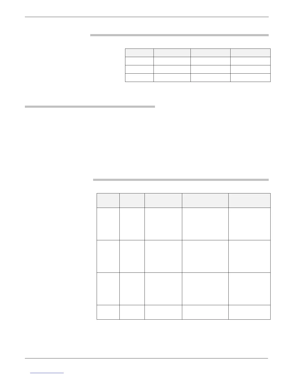
Table 3: Output voltage-level jumper settings
Axis Header 2.5V Output 10V Output
X X9 1-2 2-3
Y X14 1-2 2-3
Z X19 1-2 2-3
Power & Noise Configurations
There are three 12-pin jumpers that route the sensor output signals to the
desired amplifier – low-power or low-noise. They also configure the output
as either single-ended or differential.
Note: When using the low-noise amplifier, be sure that jumpers are also
installed across headers X21 and X22 to the power amplifier. Refer
to the table below to configure the amplifier.
Table 4: Amplifier configuration
Axis Header Low-power
Amplifier *
Single-ended low-
noise amplifier
Differential low-
noise amplifier
X
H2
1-3
2-4
7-9
8-10
3-5
4-6
9-11
8-10
3-5
4-6
9-11
10-12
Y
H3
1-3
2-4
7-9
8-10
3-5
4-6
9-11
8-10
3-5
4-6
9-11
10-12
Z
H4
1-3
2-4
7-9
8-10
3-5
4-6
9-11
8-10
3-5
4-6
9-11
10-12
Power
Jumper
X21 and
X22
Out In In
* Differential operation of the low-power amplifier is not possible.
 Loading...