DOCUMENT 301900, REVISION D
26 EPISENSOR USER GUIDE
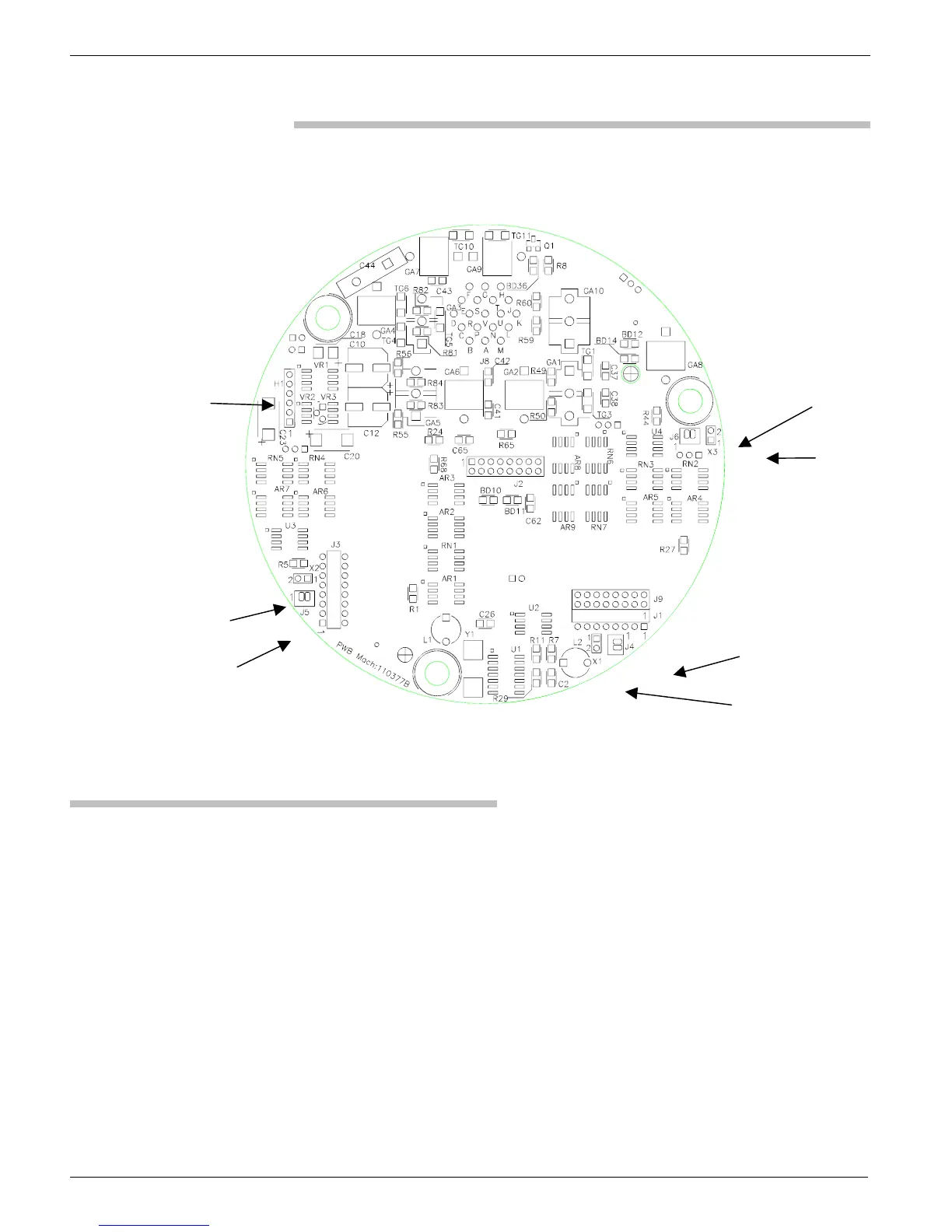
Figure 16: Bottom view of oscillator board with headers indicated
J6
X3
J4
X1
X2
J5
H1
Output Voltage Level
There are three, 3-pin jumper-header configurations that control the output
voltage level. While referring to Table 3, install one jumper at each
connector location to select the voltage output level for that axis. For the
2.5V output, install the jumper between pins 1 and 2; for the 10V output,
between pins 2 and 3.
This output level refers to the voltage from the pin to ground. Thus, if you
configure the unit for a 2.5V output voltage level and a single-ended output,
you would get an output voltage of 2.5V for the full-scale signal. If you
selected a 2.5V output voltage and a differential output, you would get an
output voltage of 5V for a full-scale input, +2.5V with respect to ground on
the positive output pin and -2.5V with respect to ground on the negative
output pin.
 Loading...