DOCUMENT 301900, REVISION D
24 EPISENSOR USER GUIDE
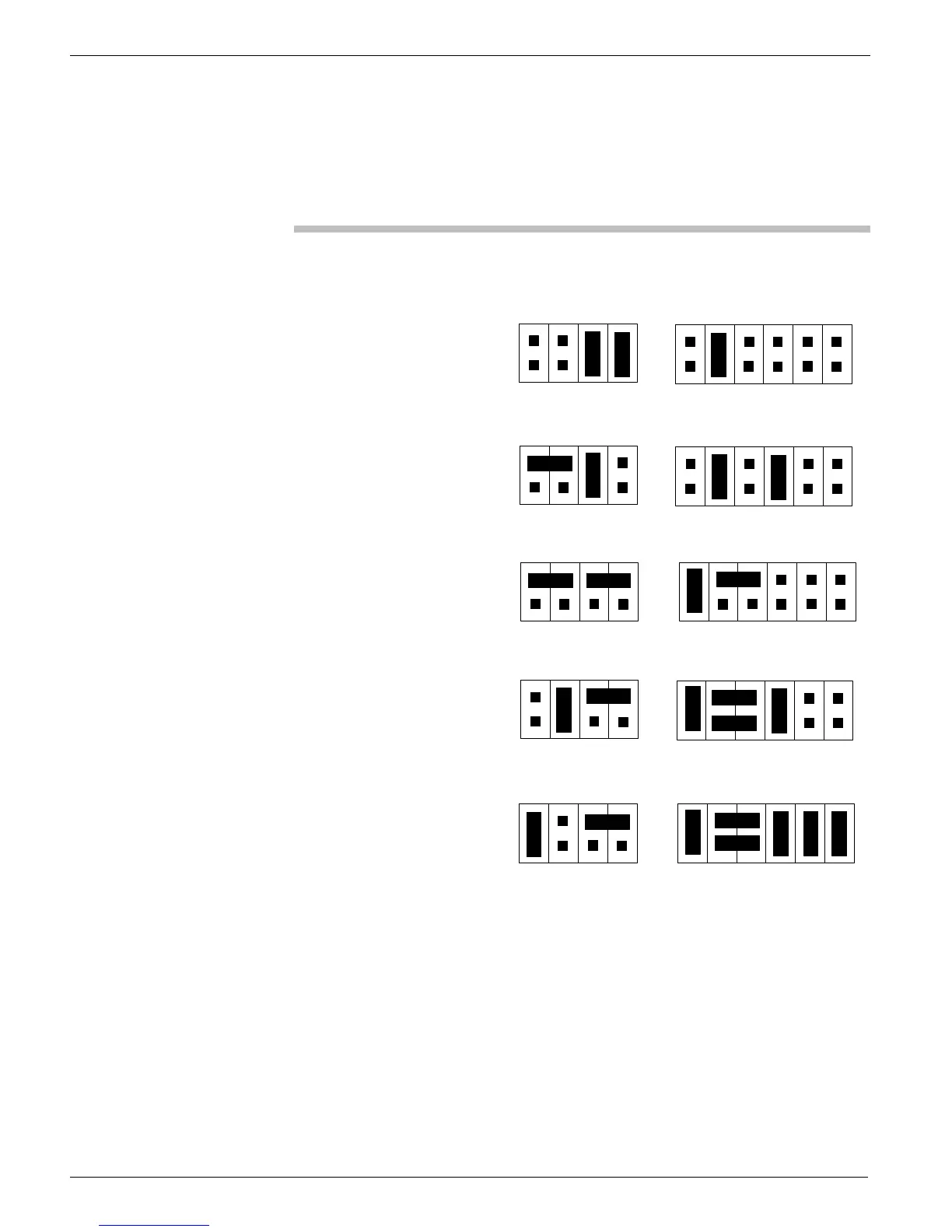
Configure each range by installing jumpers (indicated by the black
rectangles) as shown in the figure below.
Note: For clarity, we have numbered each connector pin in the figure
below, however, only #1 will appear on the actual feedback board.
Figure 14: Full-scale range jumper settings
1 3
57
2 4 6 8
Header X1
9 11
10 12
1
3
57
2 4 6 8
Header X4
1/4g
1 3
57
2 4 6 8
9 11
10 12
1 3
57
2 4 6 8
1 3
57
2 4 6 8
9 11
10 12
1
3
57
2 4 6 8
1 3
57
2 4 6 8
9 11
10 12
1
3
57
2 4 6 8
1 3
57
2 4 6 8
9 11
10 12
1 3
57
2 4 6 8
1/2g
1g
2g
4g
 Loading...