DOCUMENT 301900, REVISION D
EPISENSOR USER GUIDE 59
Figure 29: Outer foil tape and drain-wire shrink tubing
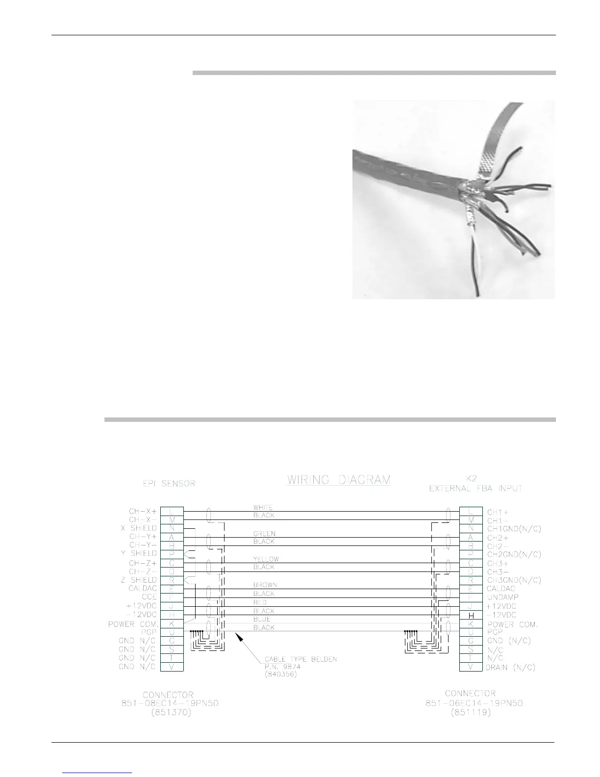
3. Now insert the twisted pairs of wires into the grommet. Use the
schematic in Figure 30 to find the proper wire-to-solder cup
locations. Be sure to follow the proper half of the schematic
below, depending on whether you are currently assembling the
recorder end or the EpiSensor end of the cable.
Figure 30: Schematic of EpiSensor cable to both mating connectors
 Loading...