KINOVA
®
Gen3 Ultra lightweight robot User Guide 41
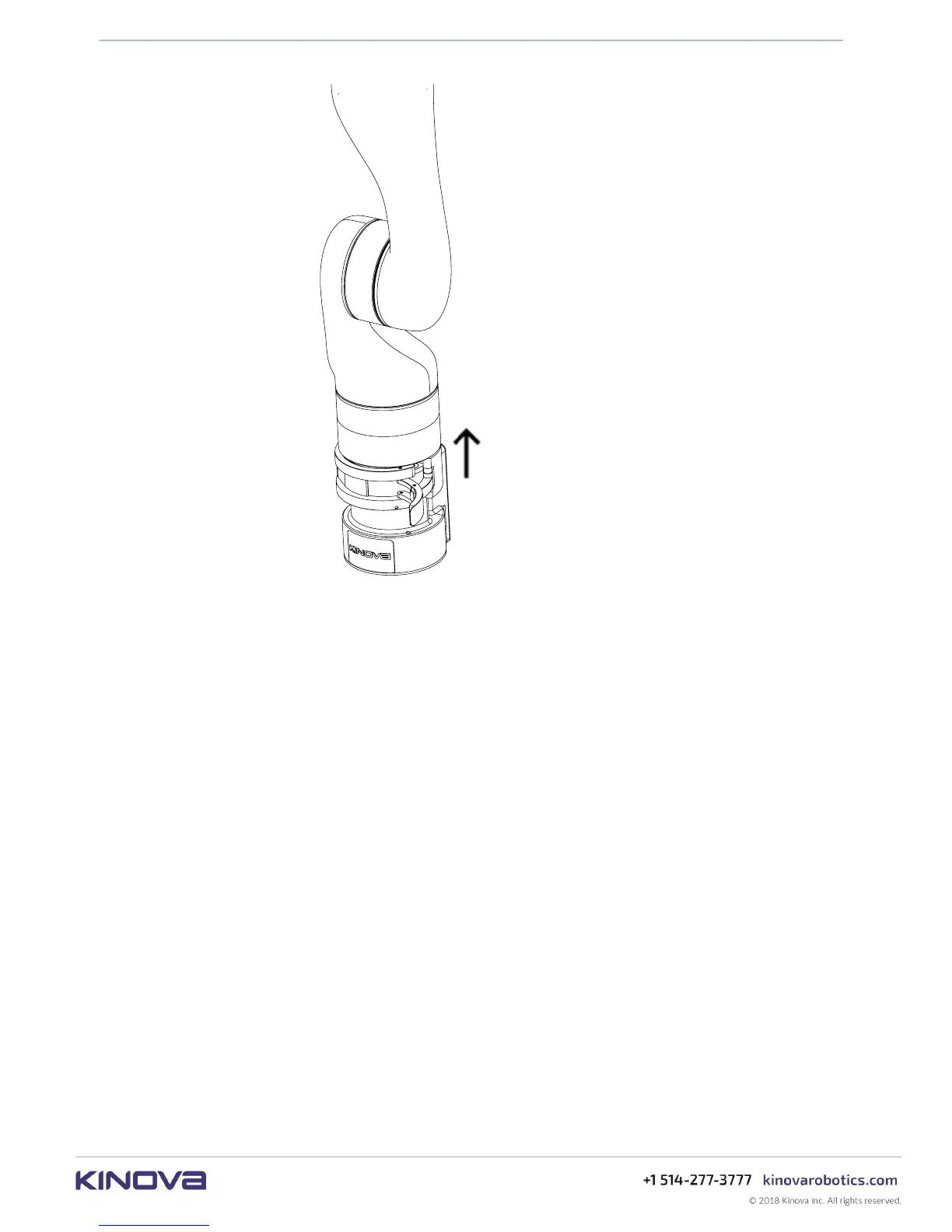
Figure 14: Base shell and arm removal
The controller features a locking screw within the mounting hole on the front bottom left (from
the perspective of an observer behind the connector panel). Turning the locking screw with a
3 mm hex key clockwise will cause the screw to go forward and protrude through a hole above
the top surface of the controller a few mm until it reaches the end of its travel. If the base shell
is already clamped onto the controller when this is done, the set screw will interface with a
mechanism on the clamp and prevent the clamp from opening until the set screw is withdrawn.
This serves as a safety mechanism. There is a hole on the clamp where the end of the lock screw
can be seen when it is fully engaged. Confirm visually that the lock screw is not engaged before
trying to open the clamp.