KINOVA
®
Gen3 Ultra lightweight robot User Guide 42
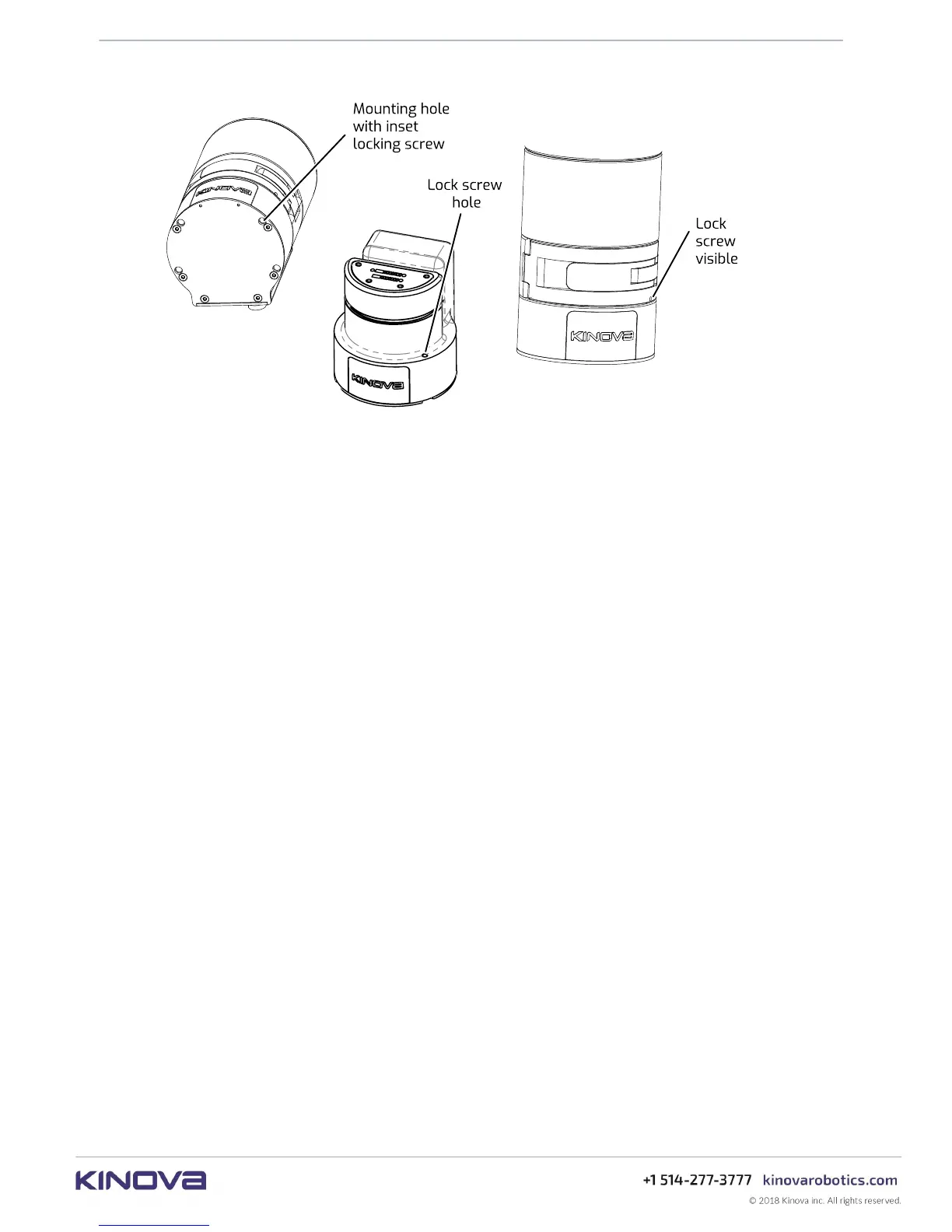
Figure 15: Lock screw mechanism
Controller connector panel
This section describes the controller connector panel of the robotic arm.
The controller connector panel is located at the rear of the controller. It features the following
elements:
• On / Off power switch
• blue power LED indicator
• red / amber / green status LED indicator
• HDMI Out (camera video*)
• Micro USB (for firmware updates)
• USB 2.0, type A - qty 2 - for wired controller. Top port 1 A for charging. Bottom port 500 mA
max, for peripherals.
• RJ-45 Gigabit Ethernet (LAN)
• Binder-USA 09 0463 90 19 (joystick, discrete I/O, E-Stop, expansion)
• Lumberg 0317 08 (power)
Note: Cables connected to the base controller must be less than 3 m in length. If not, you must
perform a risk analysis. Cables longer than 3 m can potentially have an effect on radio frequency
emissions and the immunity of the product.


 To Next Page