KINOVA
®
Gen3 Ultra lightweight robot User Guide 64
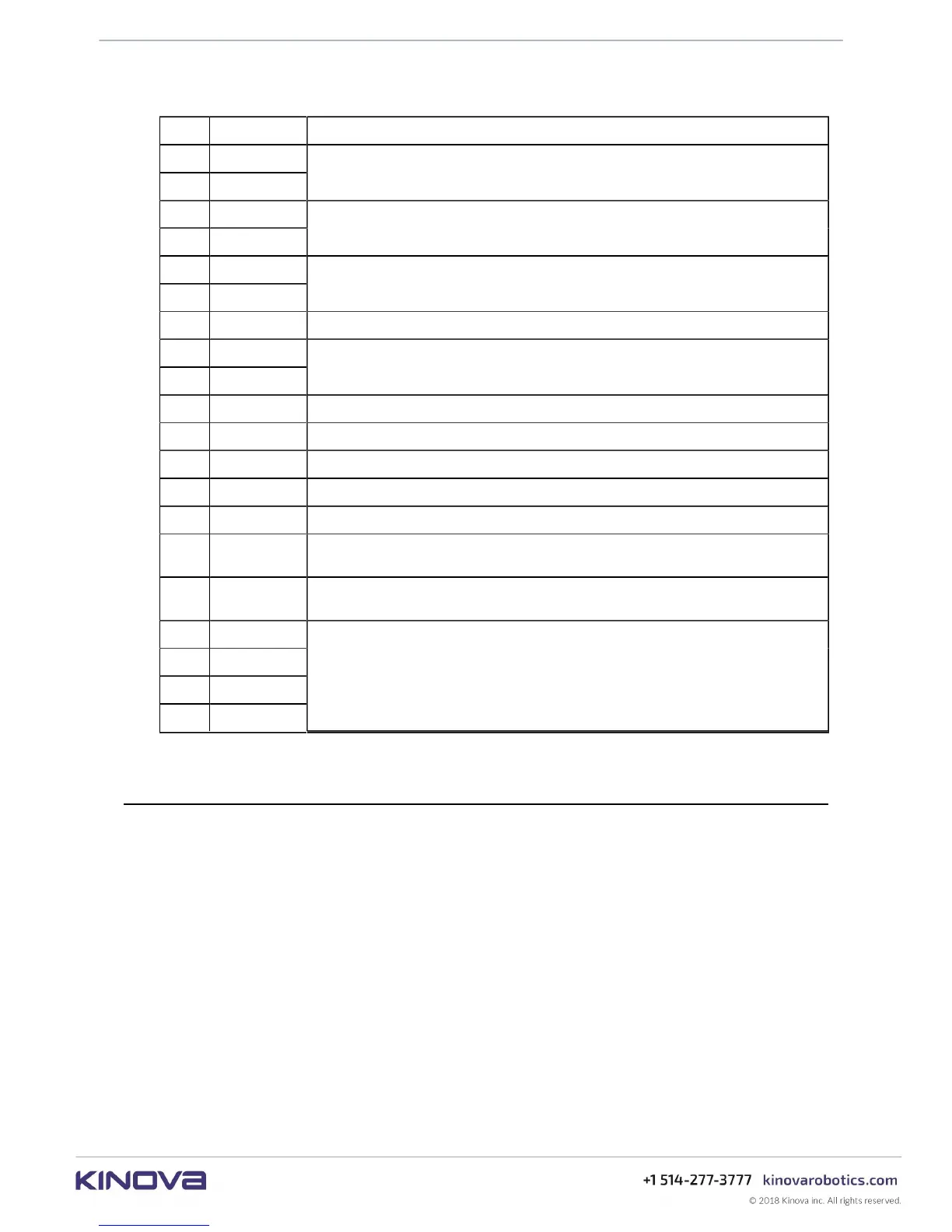
Table 23: Interface module user expansion pinout
Pin Name Comment
1 +24V USER
2 +24V USER
24V / 0.5A power; a protection device limits current shared between gripper and
user expansion port to 1A total.
3 GND
4 GND
power return path
5 ETH_RX_P
6 ETH_RX_N
Ethernet Rx 100Mbps (connected with EXP bus)
7 GND signal return path
8 ETH_TX_P
9 ETH_TX_N
Ethernet Tx 100Mbps (connected with EXP bus)
10 GND signal return path
11 +3V3 3.3V / 100 mA; can be used for small IC or sensor*
12 UART_TXD signal 3.3V*
13 UART_RXD signal 3.3V*
14 GND signal return path*
15 I2C_SCL
I
2
C clock - 3.3V*
16 I2C_SDA
I
2
C data - 3.3V*
17 GPIO1
18 GPIO2
19 GPIO3
20 GPIO4
General Purpose Input / Output 3.3V*
* to be implemented in future software release
Spring-loaded connector pinout
This section describes the pinout of the spring-loaded connector.
The spring-loaded connector pin assignment is described in the table below.