58
Chapter 1 Handling the Product
Installation (continued)
1
InstallationInstalling the Trolley Combined Model
■
Installing the Trolley Combined Model
■
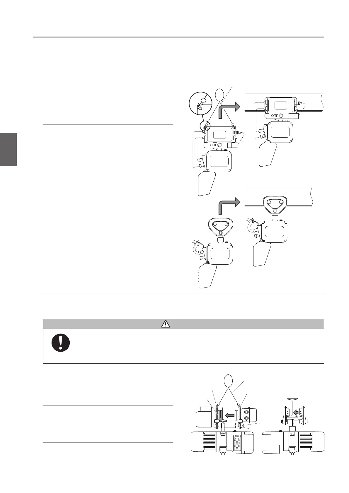
Mounting the Hoist to the Travel Rail
Sling
Hole B
Frame G
Frame S
Sling
Hole A
Lifting Shaft
3) Install the electric chain hoist combined
with the trolley to the rail from its one
end
2) Set the wheel at G side of the Trolley
Frame on the running face of the Travel
Rail. Then push the Frame S into the
Frame G.
1) Assemble the Trolley temporarily using
the hole B of the Suspension Shaft and
install the electric chain hoist from the
bottom side of the Travel Rail.
●
When the gap between the rail end the wall of the housing is scarce
3) Insert the Shaft Stopper Pin into the Hole
A of the Suspension Shaft. Then mount
a split pin securely.
• Securely support the electric chain hoist Mode ER2 not to tilt.
Failure to comply with this instruction causes bodily injury or loss of property.
Mandatory
CAUTION
1) Make sure that the dimensions of the
Trolley Frame satisfy the size of the rail
to which the trolley is installed.
2) Make sure that the rail is set to a level.

 Loading...