60
Chapter 1 Handling the Product
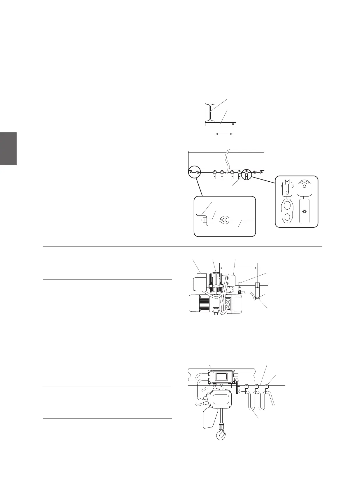
Messenger WireConnection Box
Cable hanger
Power Cable
Wire Guide
Pan head screw
Messenger Wire
Wire support bar
Rail
Wire support bar
Beam
Connection Box
Cable support arm
Motor
A
A
Cable Hanger
Wire bolt
■
Power Cable Layout for Motorized/Manual trolley type
• In the standard specification the Suspender is provided. T-shape Suspender and angle type Suspender are also
available as optional parts. T-shape Suspender can be applicable to curved rail, however, the application method
differs depending on the condition such as radius of curvature. In such case, contact KITO.
2) Tie the Messenger Wire passed through
the Cable Hanger to the Wire Support
Bar with two Wire Bolts.
•
The recommended mounting interval of the
Cable Hangers is 1.5 m to 2 m.
•
Use steel wire of 3 to 6 mm in diameter for the
Messenger Wire.
1) Mount the wire support bar at the both
ends of the rail.
3) Loosen two pan head screws and
remove the end clip of the wire guide.
4) Pass the Messenger Wire through the
groove of the messenger guide. Mount
the end clip with two pan head screws.
•
The dimension A between the side face of
the rail and the groove of the wire guide must
be same as that of mounting hole of the Wire
support bar for the Messenger Wire and the
side face of the rail.
5) Fix the Power Cable to the Cable Hanger.
6) Mount the Cable Support to the Cable
Support Arm.
7) Insert the Power Cable into the
Connection Box of MR2 and connect it
to the terminal panel.
• Connect wires correctly according to the wiring
diagram affixed on the Connection Box.
1
InstallationInstalling the Trolley Combined Model

 Loading...