105
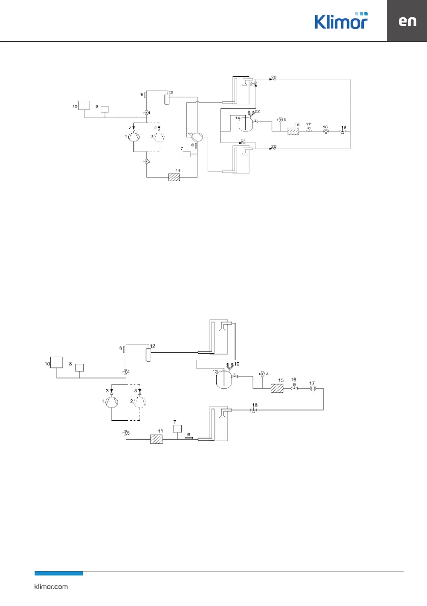
Fig. 81 Construction of HPM.d cooling system on Digital Scroll compressors
Description of the scheme
Compressor (marked by a dashed line only in tandem system).
1) Digital Scroll compressor
2) Return valve
3) On/o compressor (for larger systems)
4) Compressor shut-o valve
5) Compressor shut-o valve
6) Expansion valve cooling medium temperature sensor
7) Low pressure transmitter for the cooling medium of the expan-
sion valve
8) High pressure transmitter for the cooling medium of the
expansion valve
9) Stamping temperature sensor
10) High pressure switches
11) Suction mechanical lter
12) Oil separator
13) Four-way valve
14) Freon tank
15) Ball valve for freon loading
16) Dehydrator lter
17) Electromagnetic valve
18) Sight glass
19) Expansion valve
20) Return valve
21) Return valve
22) Safety valves
Fig. 82 Construction of CM.d type cooling system with Digital Scroll compressor
Description of the scheme
Compressor (marked by a dashed line only in tandem system).
1) Digital Scroll compressor
2) On/o compressor (for larger systems)
3) Return valve
4) Compressor shut-o valve
5) Compressor shut-o valve
6) Expansion valve cooling medium temperature sensor
7) Low pressure transmitter for the cooling medium of the expan-
sion valve
8) High pressure transmitter for the cooling medium of the
expansion valve
9) Stamping temperature sensor
10) High pressure switches
11) Suction mechanical lter
12) Oil separator
13) Freon tank
14) Ball valve for freon loading
15) Dehydrator lter
16) Electromagnetic valve
17) Sight glass
18) Expansion valve
19) Safety valves


 To Next Page