92
EVO-S, EVO-H MODULAR AIR HANDLING UNITS
OPERATION AND MAINTENANCE MANUAL
4.9 VF Fan
The purpose of the fan is to force the air ow at a certain
ow rate and pressure. The fan is powered directly by the
electric motor shaft through a frequency converter (inver-
ter).
Motor power supply: 1×230V or 3×400V 50/60Hz.
PF (plug-fan) type fans with direct drive with sheet steel or
plastic impellers and direct drive fans with EC motors are
used.
The fan unit is mounted on a frame and is xed to the oor
through vibration dampers. The fan inlet ange is connec-
ted to the suction chamber diaphragm by means of a exi-
ble stub or by a rubber seal. The elastic stub and the rubber
seal prevent the transmission of vibrations.
For smaller fans, the inlet funnel, as well as the entire fan
unit, is independently xed to the section diaphragm.
NW units intended for operation are equipped with a servi-
ce switch that transmits the ON/OFF signal to the automa-
tion system.
The maximum air temperature at the air handling unit ope-
ration is +45˚C, however, due to the acceptable operating
temperature of the electric motor, it is necessary to take into
account the power drop according to the table below.
Table 19 Power correction factor for electric motors depending on ambient temperature
Power correction factor depending on the ambient temperature
Max. ambient temperature °C 40 45 50 55 60
P/PN % 100 97 93 87 82
4.9.1 Operating instructions for fan units
Prior to commencing any works on the unit and when remo-
ving the inspection panels, one should make sure that the
unit has been disconnected from power supply, the rotor is
fan not turning, the fan motor has cooled down and that the
system has been secured against accidental start-up.
In case of an fan the following should be checked:
• before starting the fan, remove the safety components
of the fan assembly shock absorbers, whiich are moun-
ted during the transport,
• whether the rotor is clean (clean with a vacuum cleaner
and clean wet with a mild cleaning agent),
• whether the rotor turns easily,
• whether the rotor is balanced and does not run out,
• whether it has not moved in relation to the nozzle (di-
mensions of appropriate slots retained),
• condition of shock absorbers,
• all mounting bolts (if necessary, they should be tightened).
In case of an electric motor the following should be
checked:
• correct xing of all mechanical and power connections,
• quality of conductors and isolation
• whether there are any discolourations
• isolation resistance of windings
• that there are no grease leaks
• casing soiling (clean dry with a soft brush or blow thro-
ugh with compressed air).
The units are equipped with direct drive fans of „plug-fan”
type as standard. The types of fan and motor bearings used
are specied in the Quality Control Certicate.
The bearings are factory lled with lithium grease charac-
terized by high mechanical stability, resistance to aging,
anticorrosion properties, operating range -30 ÷ +130˚C. The
grease content under normal operating conditions is su-
cient for the whole bearing life.
4.9.2 Fan inverters
In case of internal units, Danfoss FC51 or Eura Drives frequ-
ency converters (inverters) are used. External versions of the
units are supplied with IP65 or Danfoss FC51 inverters.
Inverters with IP65 are only available on delivery with fac-
tory automation because they must be parameterized via
Modbus communication.
Heat recovery inverters (for rotors and glycol pumps) are al-
ways the same brand as the inverters used to drive the fans.
4.9.3 Pressure measurement orice
After start-up of the air handling unit, it is recommended to
measure the actual intake and outlet air ow rate.
For this purpose, EVO series air handling units can be equip-
ped with a connection set for measuring pressure drop on
the orice. Outside the fan section, two measuring stubs are
mounted to which a pressure transducer or pressure gauge
is connected in order to measure the dierential pressure
pw.
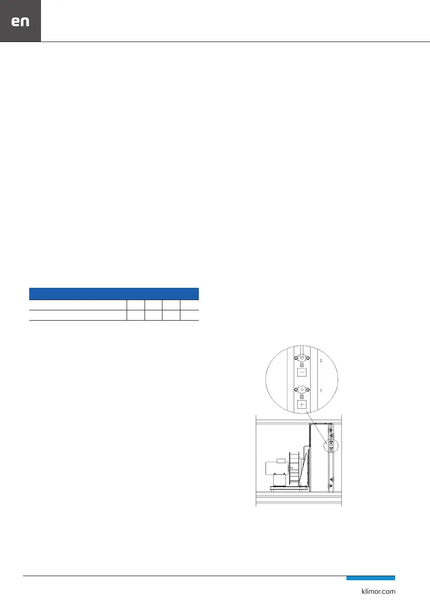
Fig. No. 71 Diagram of the fan section with mounted stubs for measuring the output
1 - mounting stub connected to (+) pressure gauge; transition to
the suction chamber of the fan
2 - mounting connection to (-) pressure gauge; connection to
fan nozzle