95
4.11 RR rotary exchanger
In RR sets, heat recovery takes place in a rotary regenera-
tor, with a recovery eciency of up to 85%. Outlet warm air
ows through the rotor section and heats it up. The rotor
transfers heat from the heated part to the cold air in the in-
take part. For summer conditions it is also possible to reco-
ver cold and humidity.
Rotary exchangers can be used in cases where a slight
mixing of the outlet and intake air is possible. The internal
tightness is dened above 97% when the rotor is installed
on the suction side of the fans.
The rotary heat exchangesr includes a rotary wheel and a
drive mechanism. A purge sector is mounted on the rotor’s
supporting construction, which prevents excessive leakage
of the exhaust air.
The section casing has an inspection cover allowing access
to the drive mechanism and the rotor.
Depending on the size of the unit, the rotor set can be built
into the unit or be a separate section.
The rotor is made up of layers of aluminium foil winded on
the axis of rotation, alternately smooth and corrugated,
forming channels for airow. To recover the latent heat re-
sulting from the humidity dierence, the foil is additionally
covered with a layer of hygroscopic material.
The drive mechanism consists of a belt transmission, elec-
tric motor (OJ-MRHX) and motor base that automatically
adjusts the belt tension.
The motor is supplied with an OJ-DRHX controller and both
units are connected by a factory-supplied wire.
OJ-DRHX is equipped with advanced software to monitor
the rotation of the rotary exchanger, which means that no
additional control is required to break the drive belt in the
form of an inductive sensor or other solution. The combi-
nation of high stepper motor torque and Field Oriented
Controls (FOC) technology provides an innovative solution
and increased eciency. The automation uses a feedback
signal from the motor to make sure that it selects exactly
the required amount of current to achieve the required spe-
ed and torque.
The exchanger should be equipped with an anti-frost sys-
tem, which will protect the device against the eects of ex-
cessive cooling of the exhaust part of the exchanger.
The protection consists of (on delivery of the manufac-
turer’s automation):
• dierential pressure sensor (pressure switch) before and
behind the exchanger on the exhaust air side,
When the pre-set pressure drop on the pressure switch is
reached, as a result of the exchanger defrosting, the con-
troller sends a signal to the inverter to smoothly reduce the
rotor speed (system with inverter).
NOTE: The rotary exchanger is supplied without a frost
protection system as standard. The type of system is deter-
mined by the ventilation and automation system designer.
A pressure system is recommended. The pressure switch
setting should be 150% of the designed air pressure drop on
the exchanger on the outlet side.
The value of pressure drop is given in the technical data of
the air handling unit.
4.11.1 Technical parametres of rotary drivesr
Detailed data on the technical characteristics of rotor dri-
ves are available in a separate technical documentation:
KLIMOR_DTR_EVO_RR_CS_057.x.x_ issued with the AHU.
4.11.2 Operation of the rotary exchanger
The rotary exchanger should be inspected every 6/12
months. Aluminium lamellas can get dirty. Before clean-
ing rotary exchanger sections, the neighbouring sections
should be secured.
Clean with a vacuum cleaner with a soft suction nozzle on
the side of air inlets or blow through with air in the direction
opposite to the airow in the exchanger. The drive belt of
the rotary exchanger is an operating element and should
be shorten if an incorrect tension is noticed.
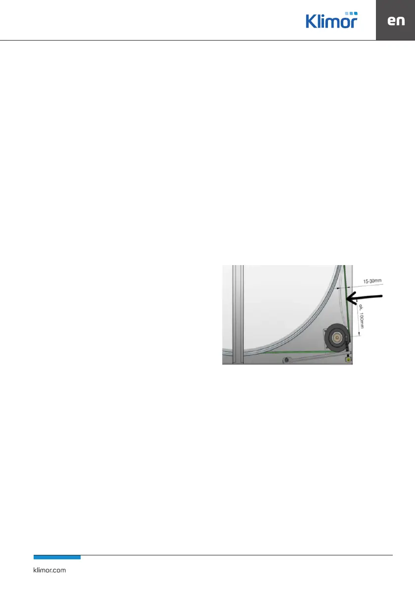
Fig. 75 Regulacja pasa napędowego
The tension of the drive belt must be controlled by pressing
the strap with moderate force with the nger at a distance
of about 100mm from the axis of the pulley. The deeeation
of the belt should be 15-30mm - as in the gure.
In case of greater deection, the belt should be shorte-
ned. For this operation, remove the belt from the pulley,
unscrew the connector (clasp), shorten the belt by the
required number of parcels of length (the graduation is
determined by holes in the belt), attach the clasp, turn
the clasp, put the belt on the pulley and make a deection
attempt.