74
EVO-S, EVO-H MODULAR AIR HANDLING UNITS
OPERATION AND MAINTENANCE MANUAL
Table 7 Dimensions of glands depending on the size of the unit
Motor power [kW] Size of the gland
< 3
3÷15
15÷30
30
P…11
P…16
P…21
P…29
Before connecting the motor to the installation, check the
resistance of the windings to ensure that they are not dam-
aged by humidity during storage.
Failure to do so may cause damage (combustion) to the
motor at start-up. When connecting motors and other elec-
trical equipment and components, it is essential to observe
the health and safety requirements contained in the rele-
vant standards and regulations for installing and operating
electrical equipment.
The electrical installation should meet the requirements
specied in the following standards and regulations (PN-HD
60364-1:2010; PN-HD 60364-5-54:2011 - Low voltage elec-
trical installations).
If the electrical switchboard is located in a dierent room
than the unit, it is absolutely necessary to install a START-
STOP switch (with interlock) in the room where the unit is
installed (as close to the unit as possible) for service switch-
o of the unit. The service switches, providing the ON/OFF
signal for the unit automatic system, are standard equip-
ment of the unit.
3.5.3 Draining out condensate
In the drip trays of the cooling block, humidier, cross-ow
exchanger and cooling set, there are drain stubs mounted
outside the unit. For AHU sizes 0230 and above, due to their
width, the connections are located on both sides of the unit.
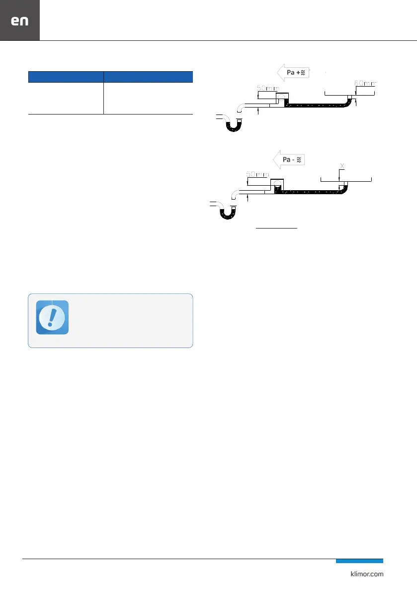
Drain traps should be connected to the stubs to ensure
proper condensate drainage and prevent air suction. Traps
are included in delivery of the unit.
The trap used is an all-purpose device and may work on the
suction (underpressure) and pressing (overpressure) side
of the fan. The only requirement is a correct installation in
terms of the direction of ow on the condensate system -
the correct direction of installation is shown on the lid.
For a trap working on underpressure an appropriately
high terminal should also be made out of supplied PVC
pipes, working out value X where the trap is going to
operate.
For a trap working on overpressure, additionally the lid
should be opened, the black rubber plug removed, and
then the lid should be closed. The siphon trap set is also
equipped with additional installation instructions.
Fig. 37 A trap working on overpressure P+
(
Pa
pressure below atmospheric
)
10
+10mmX=
Fig. 38 A trap working on underpressure P-
3.6 Unit start-up
Start-up and operation of the air handling units may be per-
formed by authorized persons with theoretical and practical
knowledge of a given air conditioning or ventilation system
Before start-up:
1. Check the correctness of connection and tightness of in-
stallations connected to the unit.
2. In the ltering block, remove the foil from the lters (if
new), check cleanliness of the lters and their mounting in
the guides.
3. Check the xing of humidier (if any), heaters and coolers
along with their equipment.
4. In the fan block, check the state of fastening of the fan
unit.
5. Check the condition of electrical connections and the
wiring to avoid rubbing electric wires against moving parts.
6. Check that the fan rotor does not rub against the inlet
funnel mounted on the diaphragm during rotation.
7. Check the electrical connections of the fans depending
on the power supply (3×230V or 3×400V). The type of pow-
er supply for which the fan has been prepared should be
checked in the unit’s KDC. On the motor nameplate, check
the method of motor connection for a given power supply.
Then connect in the required way according to the scheme
in Fig. 39.
8. In case of fans with EC motors, use the scheme shown in
Fig. 40 for single-phase and Fig. 41 for three-phase EC fans
in order to connect them.
All works shown in point 3.5 should be car-
ried out according to individual schemes and
documentation and by employees authori-
zed to perform the above mentioned works.
Additionally, it is necessary to follow the
design and assembly recommendations inc-
luded in point 8.