87
Scope of actions to be performed by the installation com-
pany:
1. Assembling and starting the air handling unit.
2. Installing the air handling unit temperature sensor (instal-
lation on the connected duct behind the module at adis-
tance of approx. 3 m).
3. Execution of passages in protective sleeves through the
air handling unit cover for gas pipe and condensate pipe.
4. Mounting the burner.
5. Building the gas installation supplying the burner, ac-
cording to the burner OMM, venting and starting the instal-
lation (gas pressure according to the burner OMM).
6. Installing the exhaust stack. Depending on the type of
gas module, the exhaust stack can also be brought out to
the opposite side of the operator
7. Mounting outside of the unit a Ø20 condense pipe and,
if necessary, connection to the condense installation on the
building.
8. Electrical connections:
a. Cable for supplying the control switchboard mounted on the
module.
b. Burner power supply cable.
c. Burner control cables.
d. Control cable - power control 0÷10V.
e. Control cable - start/stop signal.
f. Cable for supply air temperature sensor.
g. Optional cable to indicate operation and failure of the mod-
ule to the air handling unit controller.
Additionally:
• Safe access to the module and the air handling unit must
be provided on site in accordance with health and safety
rules
• The user must be present when performing any work on
the device.
• After the service has been carried out, training will be giv-
en to a person designated by the user in the operation and
use of the installed equipment.
• Temperature below -5°C as well as precipitation make it
impossible to start up the device.
• It is recommended to use condensate neutralizers if such
a requirement is made by the designer or the local Envi-
ronmental Protection Department (upon request from the
Service Department).
• After the installation is adjusted, the opening of the bypass
damper (if any) should be adjusted to the ow rate speci-
ed in the Head Oce Data Sheet.
4.7 SH Humidication
The task of humidiers is to bring the relative air humidity
to the required value. The process is carried out by means of
steam humidifying.
Humidiers with an electric steam generator
Humidiers with an electric steam generator use the ow of
current between the electrodes immersed in water to heat
up the water and generate steam.
Water containing minerals is required for the current to
ow between the electrodes. The composition of the water
should be as follows:
Required water parameters:
• pH value: 7÷8.5
• conductivity: 350÷1250 uS/cm
• hardness: 100÷400 mg/l CaCo3
• iron and magnet: 0,2 mg/l Fe+Mg
• silica: max. 20 mg/l SiO2
• no organic pollution
• supply pressure: 1÷6 bar
• temperature: 1÷40°C
• Water ow according to the requirements of a specic
generator
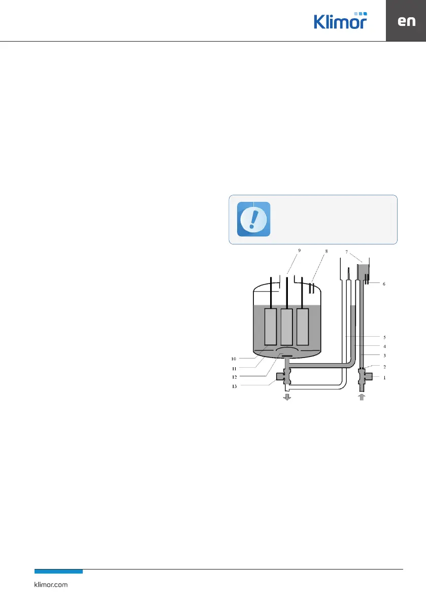
Figure 61 Construction of an electric steam generator
1. Electromagnetic supply valve
2. Flow limiter
3. Power supply cable
4. Filling line
5. Overow pipe
6. Electrodes for measuring conductivity
7. Supply tank
8. Protection against high water levels
9. Steam outlet
10. Electrodes
11. Cylinder
12. Water lters
13. Electromagnetic drain valve
If mineral concentrations in the water are hi-
gher than those given, the electrodes will be
damaged more quickly and lower ones will
reduce the eciency of the steam generator.