85
4.3.5 Operation of passive-active lters
If the G4/ISO COARSE 80% pre-lter needs to be replaced,
check the state of the electrostatic lters. Clean them if you
notice any pollution, but not less frequently than once eve-
ry 6 months.
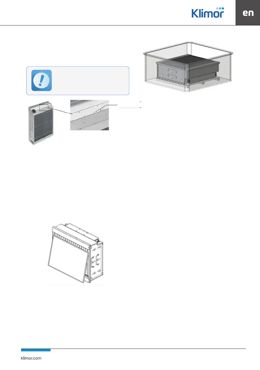
Fig. 57 Filter operation signalling
There is a green signal light in the electrostatic lter (Fig. 57),
which allows to visualize its correct operation.
A regular green signal means that the lter is working
properly, a ashing light means that the lter is faulty.
If the LED is not lit, check the electrical connections (no po-
wer supply).
To carry out correct maintenance, rst remove the pre-lter
from the cell (), lifting it by about one centimetre as shown
in the gure below
Fig. 58 Removing the pre-filter
Recommended materials for lter cleaning:
• Plastic or (INOX) container with bottom lifted to 2-3 cm
for dirt removal
• washing detergent
• gloves and goggles
• suitable clothing
• running water
Fig. 59 Filter cleaning
The cleaning process:
• dip the cell in the container as shown
• Leave it inside for the time suggested by the instructions for
use of the detergent or until the dirt is completely dissolved.
• remove the lter, rinse thoroughly under running water,
being careful not to damage the ionisation wires
• leave the lter to dry, to speed up the drying, you can place
the lter in a dry room with a maximum temperature of 60°C
• The pre-lter should be washed in the same way; during
washing, it should be handled with care to prevent defor-
mation or damage.
During each maintenance, it is recommended to check that
the lters are in good condition.
In the case of an electrostatic cell, the following items sho-
uld be checked:
• high voltage electrodes (anodes, wires)
• aluminium facings
• cathodes
• the high-voltage strip - whether it’s not burnt
• the cleanliness of the housing inside.
4.4 WH Water Heaters
A standard water heater consists of a galvanized sheet steel
housing and a CuAl package with copper tubes and alumi-
nium ns. The collectors and stubs are made of copper or steel.
The exchanger is equipped with drain and venting plugs.
During installation of the hydraulic system, it is recommen-
ded to supplement the pipes leading to the exchanger with
drain and vent valves.
When connecting the heaters to the supply system, it is ne-
cessary to follow the recommendations from chapter 4.8.1.
Dismantling the water exchanger involves unscrewing the
supply and return pipes, dismantling the casing panel from
the operating side and possibly removing the installation
from the section area. The exchanger can be removed.
In case of access to the exchanger section, also from the
opposite side of the automatic system’s operation, the pipes
are to be unscrewed
The rear cover has to be removed and the exchanger can
be pulled out.
Vertical elements of the exchanger casing that come into
contact with the unit casing are equipped with a self-adhe-
sive seal.
Before opening the inspection board, check
that the power supply of the electronic
motherboard and the electrostatic lter is
disconnected.
LED signal