89
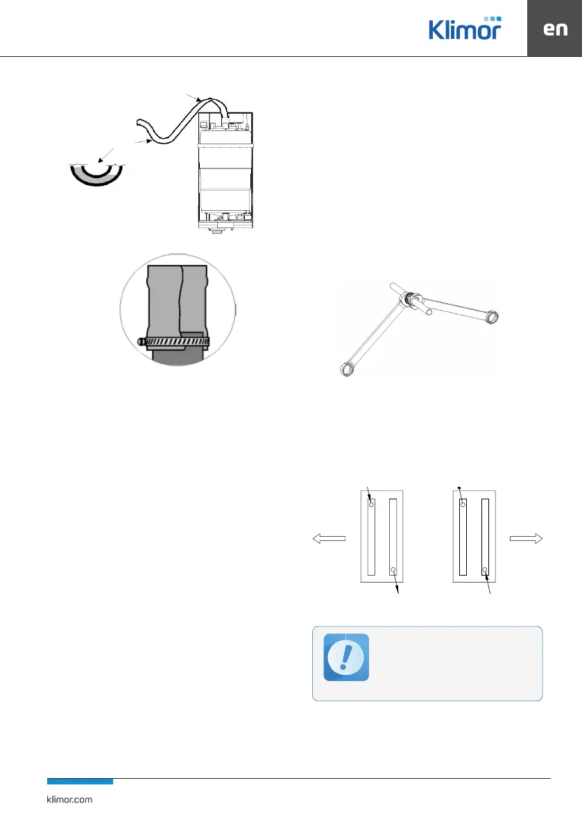
Fig. 63 Unacceptable cross-sectional constriction
Fig. 64 Installation of cable with clamps
4.7.2 Operation of humidiers
Clean and check the humidiers every 12m before the he-
ating season.
Wash the humidication sections with warm water and de-
tergent. In the case of marks of sedimentation in the drip tray,
wash it with water with the addition of a descaling agent.
Maintenance and service of the steam generator should be
carried out according to the manufacturer’s individual docu-
mentation.
4.8 WC and DX Cooling
The task of water and glycol coolers and direct evaporation
of DX is to reduce the air temperature to that required by
the design data.
A standard cooler consists of a galvanized sheet steel casing
and a CuAl package with copper tubes and aluminium ns.
The collectors and stubs are made of copper or steel.
The water and glycol exchanger is equipped with drain and
vent plugs. During installation of the hydraulic system, it is
recommended to add draining and venting valves to the
pipes led to the exchanger. When connecting the coolers
to the supply system, it is necessary to follow the recom-
mendations from chapter 4.8.1. Behind the cooler there is
acondenser for catching water drops.
For the sectional coolers, in the double exchanger version,
the condenser is mounted behind the second cooler.
Under the cooling block there is a drip tray with a stub for
condensate drainage. The trap is supplied.
The cooling and heating sections of the air handling units in
sizes 0050; 0060; 0060; 0070; 0090; 0001; 0021 are equipped
with two independent exchangers, with connection stubs
on both sides of the unit. Please consider the piping of the
exchangers also on the opposite side to the operating side.
4.8.1 Cooler and heater exchanger connections
Water heaters and coolers
Exchangers should be connected in such a way as to pre-
vent stresses that may cause mechanical damage and le-
aks. To this end we recommend appropriate compensation
of the supply and return pipeline mitigating longitudinal
expansion of the pipes. When screwing the supply and
return pipes to the exchanger stubs, use a lock key to hold
the stub pipe.
Fig. 65 Correct way of screwing the pipes
The hydraulic installation and exchanger connection should
allow their unrestrained disconnection and removal from
the unit for the purposes of repair or maintenance.
Supply and return connections are properly marked on the
service cover on AHU and their are shown on pictures.
Fig. 66 Connection of water heaters and coolers
NO
NO
Left-hand-sided version
power return
airowairow
return power
Right-hand-sided version
The connection of the water exchangers should
be carried out in a countercurrent system.
Otherwise, the average temperature dierence
between the medium in the exchanger and the
owing air will decrease, and as a result the ef-
ciency of the exchanger will decrease (for he-
aters - up to 10%, for coolers - up to 20%).