88
EVO-S, EVO-H MODULAR AIR HANDLING UNITS
OPERATION AND MAINTENANCE MANUAL
The method of start-up and operation of hu-
midiers should be carried out according to
the individual instructions of the humidier
producer
Operation principle:
When the supply valve is open, the water ows through
the supply assembly into the cylinder. After ooding the
cylinder, the electrodes heat up and steam production be-
gins. The required capacity of the generator is achieved by
setting the correct amount of current owing through the
electrodes in the control system.
NOTE:
The type of steam generator, the number and size of lanc-
es, is individually selected for the unit and the required
amount of steam.
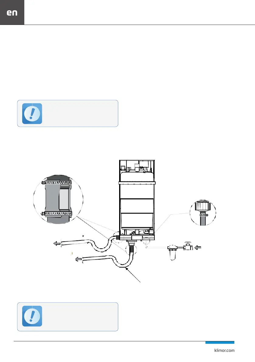
4.7.1 Humidier connection
The electric steam generator should be connected accord-
ing to Fig. 62
Requirements:
1. A shut-o valve and a mechanical lter (components not
included in delivery) must be installed on the supply line.
2. The water drain lines from the cylinder must be resistant
to temperature of 100°C.
3. An adequate gradient of the drain pipes must be ensured
(min. 5°).
4. Piping diameters are selected according to the generator
manufacturer’s recommendations.
5. A trap must be installed on the water discharge pipe, or
a suitable shape of the pipe must be created to form a trap.
6. The connection between the steam generator and the
lance can only be made by means of suitable pipes sup-
plied with the humidier.
7. When routing the supply lines of the lances, it is not
allowed to create a trap and to narrow the cross-section
Fig.63.
8. The length of the cable between the steam generator
and the lance should not exceed 4m.
9. Assembly of the cable by means of twisted clamps Fig.
No. 64.
When connecting the power supply of humi-
diers and the installation of devices, pay at-
tention to their collision-free installation with
other installations and with the unit casing
service access to the unit operation).
Slope 5°
Slope 5°
Water drain Slope
Traps
Filter
shut-o valve
supply
Fig. 62 Connection of supply and drainage to the humidier with an electric steam generator