112
EVO-S, EVO-H MODULAR AIR HANDLING UNITS
OPERATION AND MAINTENANCE MANUAL
11.7 Cable stung box
Cable stung boxes are only mounted on electric motors.
Cable stung boxes for motor connection and lighting
mounted on the enclosure (frame) only in case of delivered
and mounted control system. The stung boxes are to en-
sure proper tightness and cleanliness class of the inside of
the unit.
11.8 Materials
All the materials used to make the unit and the insert ele-
ments are resistant to commonly used disinfecting agents.
11.9 Additional construction elements in the Klimor EVO-H unit
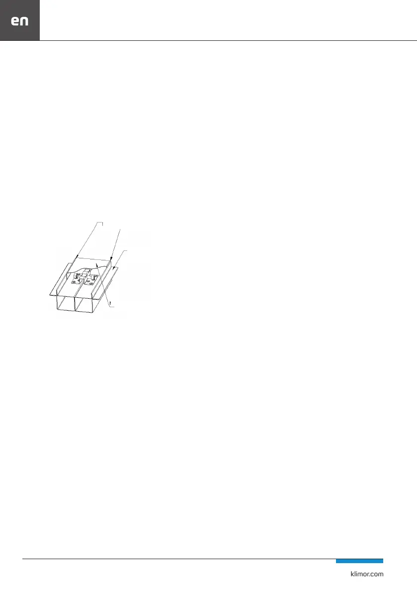
Installation of the cover channel
After mounting the block connectors inside the unit, cover
channels should be mounted and sealed with sealing com-
pound.
Fig. 91 Cover channel for connecting the control panel blocks
11.10 Design and implementation guidelines related to DIN 1946-4
Design and implementation guidelines relating to the im-
plementation of hygienic version of the air installation and
other related equipment. Conformity of design and imple-
mentation with DIN 1946-4.
Due to the technological design of air handling units in the
hygienic version in accordance with DIN 1946-4, the follow-
ing guidelines are presented for the design and execution of
air handling units to maintain the high hygienic standard of
the entire installation. A full description of the requirements
can be found in DIN 1946-4
• all components and devices included in the installation
should be easy to clean and service,
• the materials used, which come into contact with the ow
of air, must not emit substances harmful to health, bres
and odours, nor must they create conditions for the devel-
opment of micro-organisms,
• all components of the air installation must be adequately
protected until the installation is commissioned in order to
maintain the standard of hygiene,
• sucient cleaning and inspection openings of appropriate
dimensions
• must be provided in the air ducts or the section may be
dismantled,
• all signicant components of the aircraft installation must
be properly marked or described,
• it is required to place the air intake 3m above ground level
and this distance from other vertical partitions. It is recom-
mended to avoid designing the air intake in the vicinity of
air launchers, cooling towers, sources of odours or emitters
of harmful gases, as well as streets, car parks and places with
external thermal load.
• The designed air ducts must be made of mechanically du-
rable, non-corrosive and non-ammable materials, resistant
to abrasion and corrosion,
• The connections of air ducts and ttings must be made
without any faults or gaps and the fasteners must not be
in the air stream,
• sealants and seals must be hygienically approved,
• The sections of the installation intended for wet cleaning
should be designed and executed with a slope,
• The air duct between the air intake and the ventilation unit
should be as short as possible and have the possibility of
cleaning,
• the air installation for rooms of cleanliness class 1 shall be
as short as possible and the air conditioning unit shall be
located as close as possible to the rooms served,
• the dampers used on the installation must have at least
leakage class 2,
• Air dampers with tightness class 4 should be used on instal-
lations that serve rooms of dierent cleanliness classes and
on the border of areas of the same cleanliness class when it
is necessary to close parts of the installation (e.g. to replace
lters in ventilators), when it is forbidden to switch o the
whole installation,
• Hygienic exhaust air grilles with max. 0.8 mm mesh, which
are removable and washable, must be installed on the ex-
haust installations.
• The air outlet must be designed with 80% lower and 20%
upper outlet.
• At the outlets of air supply systems for rooms of cleanliness
class 1, laminar air supply units should be used,
• Depending on the local Sanitary Service, the use of air recy-
cling equipment is permitted,
• The intake and outlet elements must have current hygienic
approvals.
After completion of the ventilation or air conditioning sys-
tem, the necessary control, acceptance and validation tests
must be carried out. The tightness and integrity of lters in
ventilators should be tested by a company that has the ap-
propriate equipment and approvals. After the tests, appro-
priate protocols and documentation shall be issued.
The service technician is obliged on a pendant or sticky card
in a manner visible near the nameplate to document: the
date of the last lter replacement, the type of lter installed,
the amount of initial pressure drop and the dierential pres-
sure read during the inspection.
Sealing compound
Prole
Masking frame


 To Next Page