110
EVO-S, EVO-H MODULAR AIR HANDLING UNITS
OPERATION AND MAINTENANCE MANUAL
10. EXTERNAL VERSION OF THE KLIMOR EVO AIR
HANDLING UNITS
KLIMOR EVO units can be adapted to work in outdoor con-
ditions. The dierences between the roof version of the air
handling units and the standard version are specied below:
a) Housing
All gaps between the xed panels of the cover type and the
aluminium frame are lled with sealing compound.
b) Air intake/outlet
The air intake/outlet is made as a ventilation tting with
steering wheels and a net. Its role is to cover the air inlet/
outlet from rain, wind and solids larger than 10×10mm.
It’s screwed to the damper or the air handling unit prole.
Mounting on the front wall or other (e.g. side) wall after
equipping the air handling unit with an empty section. It is
possible to mount additional elbows or ducts.
When the inlet is mounting on the side of the unit, the sec-
tion is equipped with an a drip tray for collecting conden-
sate (rainwater).
For the facing walls of the air inlet and outlet, if the outlet
is above the inlet, additional ventilation elements (duct or
knees) should be used on one of the air direction, to elimi-
nate the possible impact of both air jets.
c) Air dampers
The shut-o dampers are mounted outside the unit. Such
location is possible by hiding the blade drive in a double al-
uminium prole. The damper actuators are covered, but the
actuators with a higher degree of protection min IP54 are
required.
d) Exchangers
Water exchangers (heaters) are equipped with anti-freeze
protection by an anti-freeze thermostat in the air (only avail-
able with the supplied complete control system).
The heater collector stubs can be led inside the unit in a way
that allows for installation of pipelines, supply and return,
through the ceiling in the space between the unit frame
or inside. It is also possible to install the exchanger control
node in an additional section.
e) Roong
Fig. 83 Installation of air handling unit roong
Each set has a roong made of galvanized or coated sheet
metal, mounted to the prole.
Fig. 84 Connecting parts of the roong
A set of roong elements is delivered on a separate pallet.
The assembly of the roong takes place after the unit has
been set up on the destination.
f) Control system
Control system can be supplied in external or internal design.
The IP65 outdoor control system’s switchgear is equipped
with a heater and thermostat. Inverters for mounting inside
the unit in the fan section.
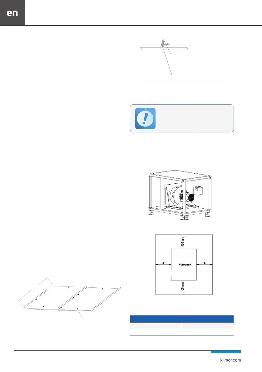
Fig. 85 Preferred place of inverters in the fan block.
Fig. 86 Free spaces required by inverters
Table 32 Free spaces required by inverters
Type of inverter Min. free space A [mm]
Installation inside the roof unit 50
Mounting outside the indoor unit 0
The AHU roong enables walking during in-
stallation.
Fill with sealing mass before
connecting the two parts
Fill with sealing mass before
connecting the two parts
Connecting roof elements 1pcs per 1m width
of the unit
Inverter
Width of the AHU