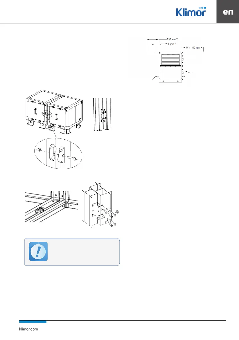
73
3.4.3 Connecting of the blocks
If the air handling unit is delivered in separate blocks, the
individual sets should be screwed together, using the con-
nectors and screw couplings provided. Before screwing
skeleton of one of the sections to the prole surfaces, a do-
uble rubber seal must be glued on.
If the joining of sections is placed between heat exchan-
gers or another section with dicult access, one of the
heat exchangers should be removed and the connectors
of both blocks should be screwed. After connecting, in-
sert the exchanger again.
Fig. 34 Connecting blocks outside the AHU
Fig. 35 Connecting blocks inside the AHU
The unit is xed to a concrete foundation frame or level-
led concrete oor. It is allowed to install the AHU without
xing the unit frame only for internal AHU. External units
mandatory require mounting to the ground (roof frame,
foundation, etc)
All sets have individual foundation frames or corners equip-
ped with Ø13 holes for anchoring or screwing to the founda-
tion. The AHU should be mounted and connected by wires
in such a way as to leave sucient space for the unit main-
tenance. Required amount of space is shown in Fig. No.36.
Fig. 36 Space required for operating the air handling unit
*- for unit sizes 5100-0720
**- for unit sizes 0230-0050
***- for unit sizes 0230-0050
Design the water drain from the trays according to Fig. 37
or Fig. 38
For split sections of the RHE, additional installation instructions
are required. Information could be nd in the OMM-KL-RR-A-
SM-GUILS
3.5 Installation and connection of the unit
After nal installation of the air handling unit, you can pro-
ceed to connect the air network, electrical, heating, cooling
and humidifying systems (the scope of work depends on
the air handling unit functional set).
3.5.1 Air system
The air handling unit with rectangular air ducts is connec-
ted by means of exible stubs, which is included as standard
in each inlet and outlet of the unit.
They counteract vibration transfers and compensate for
major deviation in the mutual position of the duct and unit
window. Ventilation ducts should be connected with the jo
int anges in the corners by means of bolts. In order for the
elastic connection to work properly, the joint sleeve should
be extended for a minimum of 110mm.
It is necessary to ensure continuity of grounding between
the air handling unit housing and the ventilation network
using the yellow-and-green wire bolted onto the throttle
valve and casing.
Ventilation ducts should have their own supports or su-
spensions.
In accordance with EN 1886, at the outlet of the unit on the
supply duct, must be installed a safety net with mash sizes
of 20x20mm, which makes re protection preventing the
transport of burning particles of objects to the supply.
Making this element belongs to th installer.
3.5.2 Power Supply Installation
For the power supply to and earthing of the electric mo-
tors in the fan block housing and for the internal pump of
the glycol system from the operating side, cable glands
can be installed. The glands are mounted on fixed pro-
files and casings.
To ensure proper operation of the functional
elements (e.g. drain from drip trays) and to
maintain the tightness of the construction,
the units should be placed on a level ground.
Operation
side
Condensate drain***