64
EVO-S, EVO-H MODULAR AIR HANDLING UNITS
OPERATION AND MAINTENANCE MANUAL
2.2.5 AHU design
Fig. 2 Ahu version
2.3 Technical acceptance
The units, when fully assembled, are subject to acceptance
of the KLIMOR Quality Control, as a result of which a certi-
cate is issued conrming that they meet the quality require-
ments and work parameters specied in the order.
2.4 Design of the units
The intake, outlet, and intake-outlet air handling units are
assembled from functional modules, also known as sections.
The designer selects the functional layout according to the
requirements of the air handling system.
The basic components of the individual modules are:
• self-supporting construction,
• functional units,
• housing components,
• unit frame (optional foundation corners).
The housing of the module are skeleton, panels, frame.
The skeleton is made of steel or composite proles, connect-
ed by corners made of constructional material; the stiening
elements are omega sectional proles, so-called „ribs”. They
are made of the same materials as the skeleton.
The sectional proles are at the same time a supporting struc-
ture for individual functional units mounted inside the AHU.
Panels are made in the „sandwich” technology. There is a dis-
tinction between: covers, service covers and doors.
Panels consist of external and internal sheet metal (gal-
vanized or galvanized and coated), separated by a prole,
eliminating thermal bridges. The space between the sheets
is lled with non-ammable mineral wool. The covers are
riveted to the skeleton. They constitute the upper, rear and
lower walls of the housing. The oor is additionally supple-
mented with a polyurethane plate, mounted from the in-
side of the casing.
The user’s interference in the supporting
structure (its dismantling, drilling, cutting
out) may result in the unsealing of the air
handling unit and loss of warranty.
Cover-type panels (xed to the frame for clamps) and doors
(closed with handles or clamps) are used from the service side.
Connections of covers and doors with the frame are sealed
with a rubber seal.
AHU skeleton is placed on the AHU frame, made of a bent
channel bar made of galvanized sheet metal and screwed to
it. Between the skeleton and the frame there is a cushioning
spacer installed. For units of sizes 5100 to 3500, foundation cor-
ners can optionally be tted in order to replace the full frame.
In the SE units sizes 0050-0021, the frame also appears un-
der the upper section.
In the frame and in the foundation corners there are holes
Ø50 for hooks to be hooked in or for the traverse pipe.
The casing is equipped where appropriate with pulse stub
pipes for connecting the lter pressure switches.
Filter and fan sections with an internal height of more than
1.6 m are equipped as standard with inspection windows
and lighting.
3. TRANSPORTATION, STORAGE, INSTALLATION AND START-UP OF THE UNIT
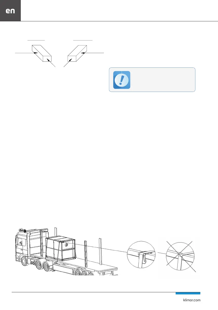
3.1 Loading and transporting of AHUs
The unit is transported to the assembly site in sets.
Use transport angles when transporting on a truck.
Fig. 3 Correct and incorrect way of transporting the AHU on a truck
Left-hand sided version
Airow direction
Right-hand sided version
Operation side
Operation side