86
EVO-S, EVO-H MODULAR AIR HANDLING UNITS
OPERATION AND MAINTENANCE MANUAL
In terms of antifreely protection, depending on the cu-
stomer’s preferences, the water heater is equipped with a
thermostat or a temperature adhesive sensor. Devices are
applied alernately.
The antifree thermostat is installed in the AHU unit around
the exchanger window - behind the heater.
The adhesive sensor is supplied in bulk and, if automatic ca-
bling is ordered, it is factory wired and installed. The sensor
must be mounted on the return collector of the heater.
4.5 EH Electric Heaters
The electric heaters installed in the units can be single or
multi-stage with dierent power distribution for each stage.
Radiant heaters with a large heat transfer surface are used
in the heaters. The heaters are factory connected to a ter-
minal strip.
A gland is mounted in the heater block cover to guide the
heater supply line. A diagram of heater connection to the
terminal strip is glued to the housing.
Electric heaters are equipped with a thermal switch protec-
ting the device against overheating, in case of air ow loss.
Such a switch, which has normally closed contacts, should
be included in the design of the control system.
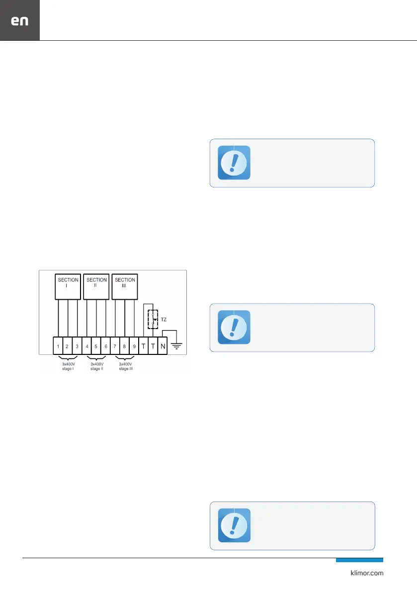
Fig. 60 Example of heater and thermostat connection to a terminal strip in a three-stage heater
4.5.1 Operation of the electric heater
The electric heater should be kept clean. Dust settling on the
heating elements hampers heat output, and as a result may
cause burnout of the heating elements and a re hazard. The
condition of the heating elements should be checked every
four months. They should be cleaned with a vacuum cleaner
with a soft suction nozzle on the side of air inlet or blown
through with compressed air. Wet cleaning is not allowed.
4.6 GM gas heating module
The gas heating module allows the ventilation air to be
heated using the heat from burning gas in the exhaust-air
exchanger. The gas is burned by a fan burner.
The gas heating module installed in the air handling units
consists of, among others, exhaust-air exchanger, fan bur-
ner, gas ow path, exhaust outlet pipe, condensate outlet
pipe and safety automation.
Fan burners used as standard equipment are in a modulat-
ed version.
For safety reasons, each size of the gas module has a de-
ned minimum and maximum air ow and minimum and
maximum burner power. Detailed technical data can be
found in the OMM of heating modules and fan burners
delivered with the unit. Non-compliance with these recom-
mendations may lead to damage to the unit.
For units with heat recovery, the gas heating sections may
be equipped with an internal exchanger bypass chamber
with a control damper. The side ow is used for units for
which the air output of the air handling unit is higher than
the acceptable amount of air owing through the exchang-
er. The quantity of bypass air is given in the technical data
of the unit and is used to adjust the damper with manual
adjustment. The fan burner and the safety automation
switchboard are mounted on the casing wall and protected
by a hinged cover. Options with an internal exchanger and
a fan burner, as well as an electric switchboard of the safety
automation are also used for these versions. Then, the entire
equipment is installed inside the section with free access
from the operator side.
The gas type E (GZ50), LW (GZ41,5); LS (GZ35) and B/P (LPG) is
used to supply the burners. The type of gas must be specied
when selecting the device and in the order.
For external versions of the units, movable covers or roong
are used for protection against rain and UV rays.
For GM gas heating modules there is a separate operat-
ing and maintenance documentation issued. During the
start-up of the unit, it is essential to comply with the pro-
visions contained therein.
4.6.1 Start-up of gas heating module
The burner is started up by the service with a certicate of
qualication issued by the manufacturer. Contact Klimor
service or burner manufacturer to arrange the start-up date.
The following conditions must be fullled before starting
the start-up and making adjustments.
The required and recorded amounts of air
owing through the exchanger and bypass
must be followed. During the operation of the
gas heating modules, do not change or adjust
the degree of opening of the heat exchanger
bypass damper.
After switching o the module, the air han-
dling unit’s supply fan should operate with
the dampers open for at least 5 minutes. The
capacity of this fan should be equal to the
capacity it last worked on.
Before starting the burner, the air handling
unit should have an adjusted ventilation sys-
tem. When adjusting the installation, the bur-
ner bypass damper should be opened as much
as possible.