90
EVO-S, EVO-H MODULAR AIR HANDLING UNITS
OPERATION AND MAINTENANCE MANUAL
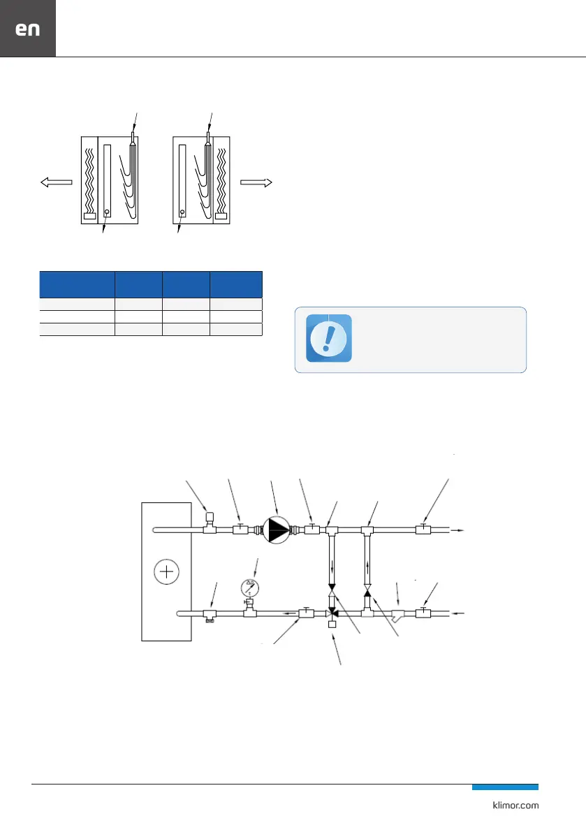
DX Cooling Coil
Fig. No. 67 Connection of DX Cooling coils
Table 18 Coil parameters
Coil
Max. work
temperature
Work pressure Test pressure
Water heater 110˚C 1,0 MPa 28 Atm
Water cooler 110˚C 1,0 MPa 28 Atm
DX cooler - 2,8 MPa 40/45 Atm
NOTE:
1. In order to protect the automatic system mechanisms aga-
inst excessive overheating, for units with heaters supplied
with medium over 100˚C, a water supply blockade should be
provided when the AHU is o (e.g. an electromagnetic valve).
2. The exchangers’ stubs should be connected in such a way
that the exchanger operates in countercurrent.
3. The diameter of the condensate tray stub pipe of the wa-
ter cooler as for the DX cooler is 32mm.
4. It is recommended to replace the drain plugs with valves
and the vent plugs with vents.
Please note that these elements are located on the exchan-
ger collectors. They can be accessed after removing the
section cover. If after installation of the exchanger supply
system access to these elements is dicult, it is necessa-
ry to lead them outside the unit in a convenient place. In
external devices, the vent and drain elements should be
protected against freezing.
5. DX coolers are lled with nitrogen at a pressure of
0.03MPa, which prevents moisture from penetrating them.
Left-hand-sided version
power power
airowairow
suction
(return)
suction
(return)
Right-hand-sided version
vent pump
T-piece T-piece
thermomanometer
STAD
balancing
valve
ball
valve
ball
valve
drain
valve
STAD balancing
valve (optional)
three-way
valve
check
valve
check
valve
mechanical
lter
ball
valve
When connecting the power supply to the heat
exchangers, care must be taken to ensure that
the pipes run smoothly with other installations
and with the unit housing (service access to the
unit operation).
4.8.2 Recommended heater mode design
Fig. 68 Example of connecting a water heater in a mixing system