- 62 -
Workshop Manual KD 441_cod. 1.5302.865_2
nd
ed_ rev. 01.
8
149
148
146
1
2
4
3
5
6
8
8
9
147
10
11
12
13
7
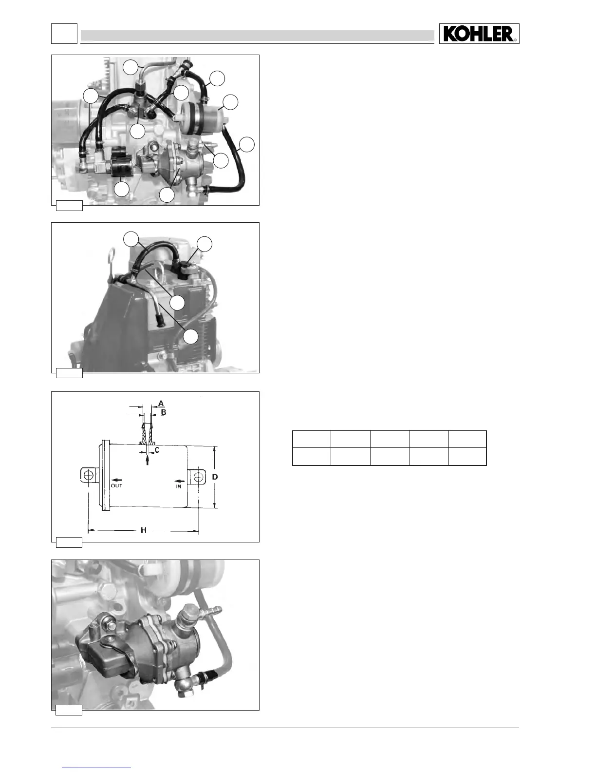
A
7.3
B
3.8÷3.81
C
1÷1.2
D
42
H
75
Fuel lift pump
The pump is the diaphragm type and is operated by a camshaft ec-
centric through a drive rod.
Tighten screws to 15 Nm.
Characteristics:
At 2000 rpm of the camshaft, the minimum delivery is 40 l/h, while the
automatic adjustment pressure is 0.5 ÷ 0.7 bars.
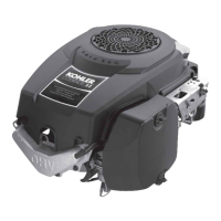
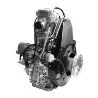
FUEL SYSTEM
Fuelling/injection circuit
Components:
1 Fuellterreturntube
2 Fuellter
3 Injection pump
4 Injector pump exhaust pipe
5 High pressure line
6 Fuel lift pump
7 Fuel pump suction (to be connected to the tank)
8 Fuel feeding tubes
9 Solenoid valve
10 Injector
11 High pressure line
12 Injector leak-off line
13 Fueloverowpipe(tobeconnectedtothetank)
Fuel lter
Dimension (mm)
Characteristics: Filtering area ...............≥ 390 cm²
Filtration level ..............≤ 7 µm
Seepage14forfuellterreplacement.
 Loading...