- 70 -
Workshop Manual KD 441_cod. 1.5302.865_2
nd
ed_ rev. 01.
9
172
173
171
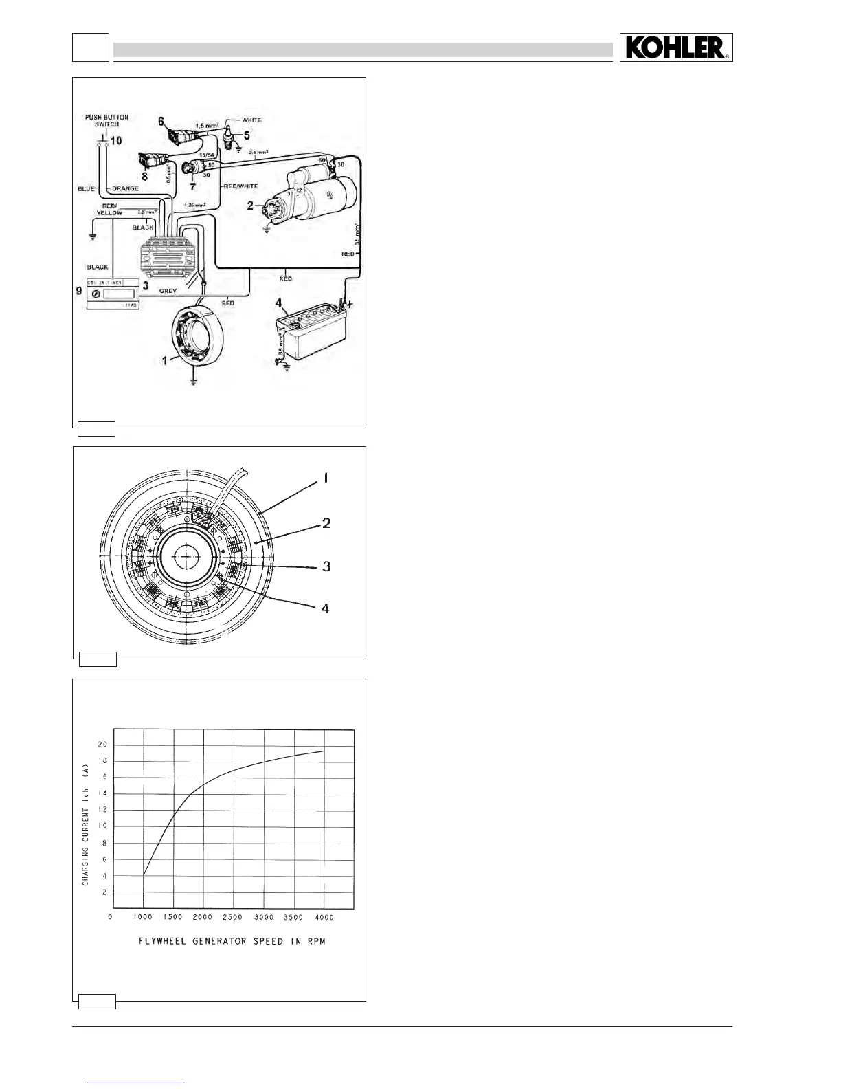
12V, 17A electric ignition diagram
Components:
1 Alternator
2 Starter motor
3 Voltage regulator
4 Battery
5 Oil pressure switch
6
Oil pressure light
7 Key switch
8 Battery charging light
9 Capacity bank
10 Push button switch
Note: The battery, which is not supplied, should have 12V nominal
voltage rating and a capacity of not less than 44 Ah / 210
Amp. of fast discharge intensity.
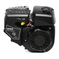
Alternator charger graph (12V, 17A)
This test has been carried out after thermal stabilization at 20°C for
2 minutes at 3000 r.p.m. with constant battery voltage of 12.5V.
The value of the power supplied with reference to the curve may
change in a range between +10% and -5%.
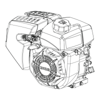
Alternator
Components:
1 Ring gear
2 Flywheel
3 Rotor
4 Stator
Thestatorxingscrewsmustbetightenedto1.2Nm.
Note: The rotor is made up by a plastoferrite ring which is xed to
ywheelwhilethestatorismountedonthecrankcase.
ELECTRICAL SYSTEM