- 66 -
Workshop Manual KD 441_cod. 1.5302.865_2
nd
ed_ rev. 01.
8
163
2
161
162
13
4
2
160
1
5
3
4 2
5
Fuel system
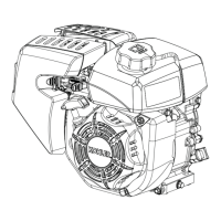
8-Proceedslowlyduringthecompressionphase.Thefuelthatows
from tube 2 will tend to diminish.
9 - Stop as soon as it creases to drip (one drop of fuel every 30-40
seconds is tolerated).
10- This is the static injection lead.
11-Useatapemeasurefromabovetheywheeltomeasurethe
distancebetweenthexedTDCreference Ag.164onthe
crankcase and the TDC reference point Contheywheel.
12-Comparethevaluefoundinthe"Conversiontablefrommillimetres
intodegrees"tondtheadvancedegrees.
13-Ifthevaluefounddoesnotmatchthespeciedvalue(see"Injec
tionadvancespeciedvalue"table),replacethepadbelowthe
injectionpump(g.165)
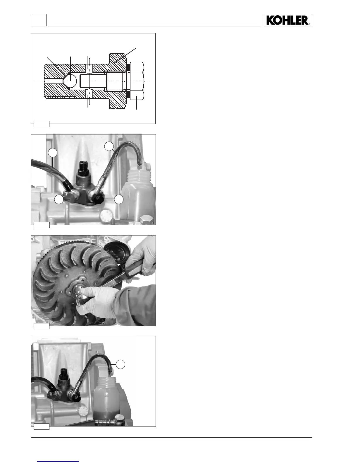
Static injection timing
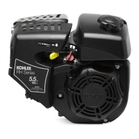
1 - Disconnect the pipe from injection pump outlet 1.
2
- In its place, assemble a clear nylon hose 2asshowninthegure.
3 - Insert a metal wire, protruding about 10 mm, into the hose to allow
an easier check of fuel leaks.
4 - Connect the injection pump intake 3 with a hose 4 to an auxiliary
tank placed at about 50 cm higher than injection pump.
5 - Fill the tank with the fuel
6-Settheowgovernorleveroftheinjectionpumpinthestop
position and lock it there.
7
-Turntheywheelintheenginerotationdirection.
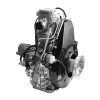
Injection pump non-return valve
In the exhaust union screw there is a non-return valve. The purpose of
this valve is to improve the injection phase by expelling the air in the
fuel and preventing it from being sucked in by the pump during the in-
take phase. This also ensures that the engine stops promptly as soon
as the stopping device is activated by means of the solenoid valve.
Outlet tting components with non-return valve
1 Outlettting
2 Ball Ø3.968 mm
3 Threaded screw
4
Ball retaining seat
5 Exhaust holes