- 74 -
Workshop Manual KD 441_cod. 1.5302.865_2
nd
ed_ rev. 01.
182
181
180
183
10
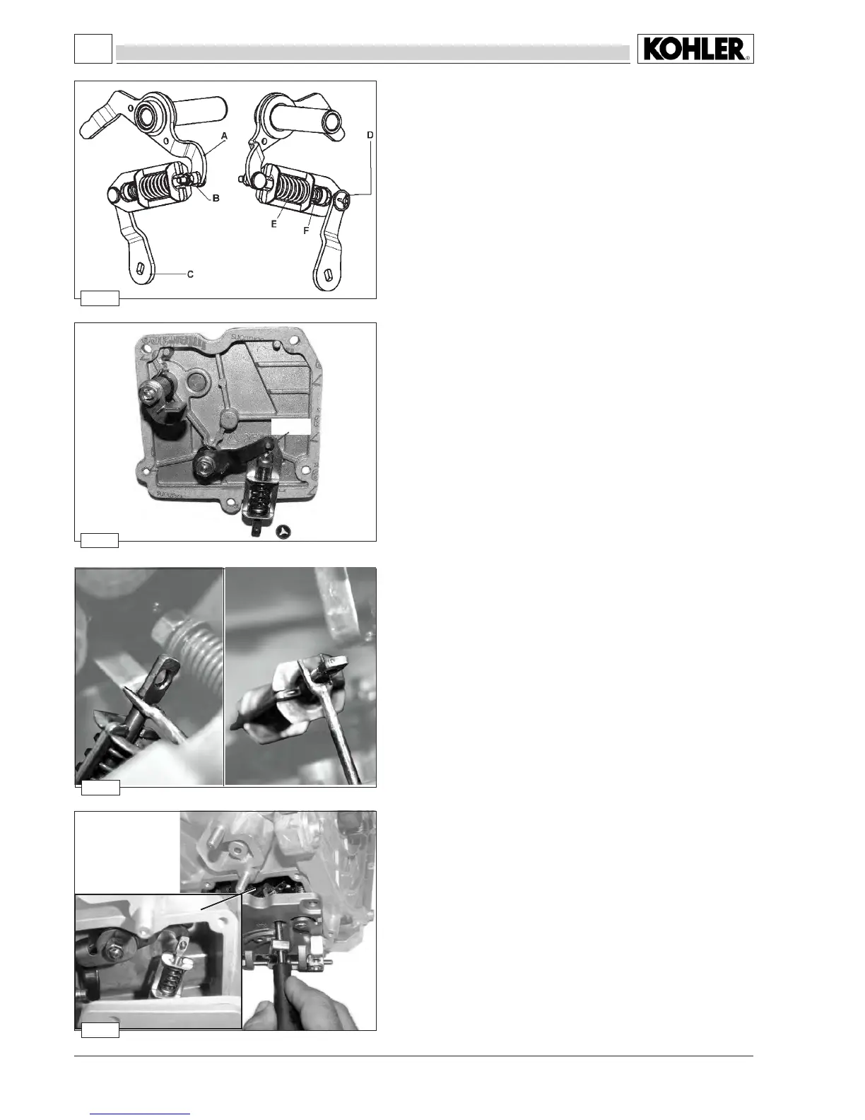
Assembly procedure for accelerator lever of speed governor with
min/max speed system
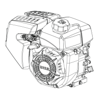
Insert the pin in the hole on the internal accelerator lever.
Mount the lock ring on the pin.
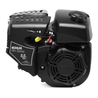
With a special fork tool matr.1460-341, take the min-max assembly as
showninthefrontandtopgure.
pin
lock ring
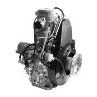
Accelerator lever for speed governor with min/max speed system
A Internal governor lever into control group
B Nut
C Internal accelerator lever into control group
D Lock ring
E Max. speed spring
F Min. speed spring
The threaded pin of the governor lever must
enter in to the hole on the min-max assembly
ADJUSTMENTS