- 65 -
Workshop Manual KD 441_cod. 1.5302.865_2
nd
ed_ rev. 01.
159
8
158
1
2
A
E
B
157
3
4
5
6
E
11
10
9
8
7
12 12
D
C
A
B
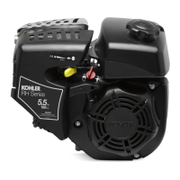
Injection pump retting
The plunger is tted with helix E facing towards the outlet union A;
ifitismistakenlyttedwiththehelixfacingtheintakecouplingB the
injection pump no longer operates (there is no danger of engine ru-
naway);completerettingfollowingg.136.
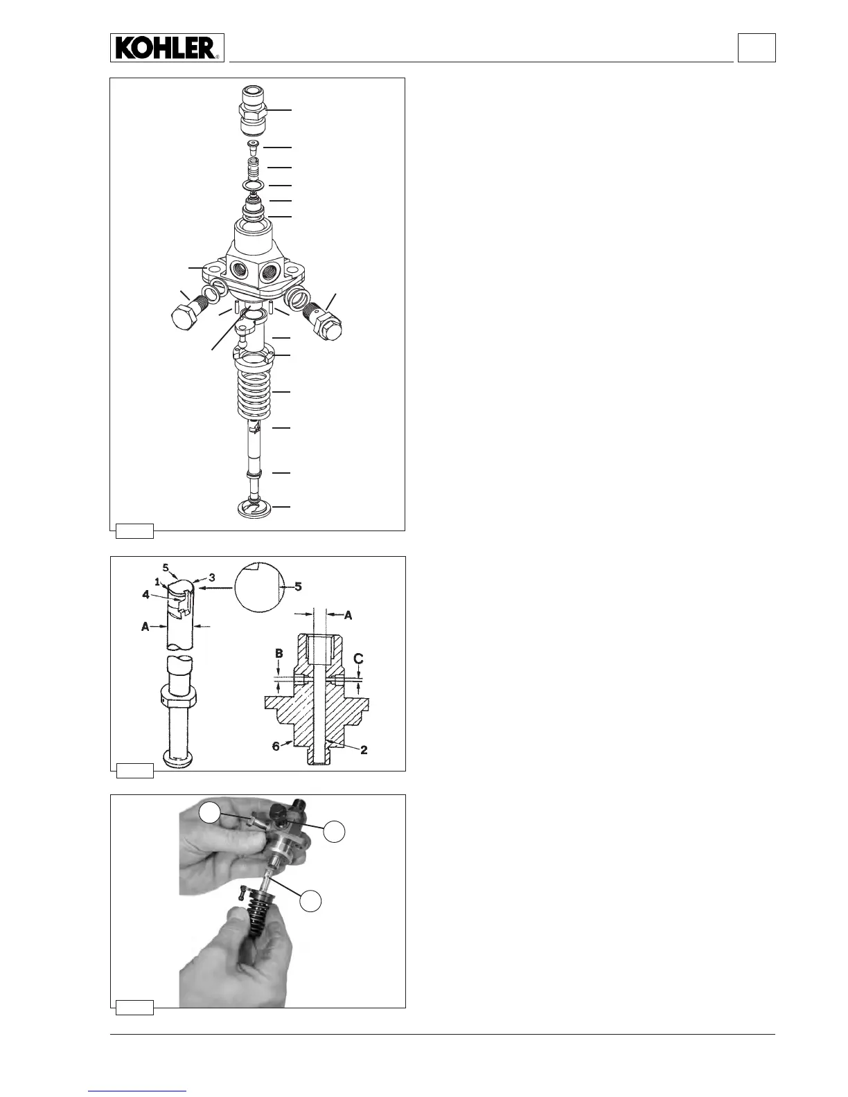
Fuel system
Injection pump components and disassembly
1 Delivery union
2 Filler
3 Spring
4 Gasket
5 Delivery valve
6 Gasket
7 Spring retainer
8 Spring
9 Sleeve
10 Rack
11 Piston (pumping element)
12
Pin
A Fuel exhaust union screw with non-return valve
B Fuel inlet union screw
C Fastening
D Plunger barrel (in the injection pump case)
E
RH helix
Demount in compliance with the numeric order.
Plate 9isheldrmbypins 12. Lever up by inserting a tool between
the plate and the body of the pump.
The volume shifted by delivery valve 5 is 21 mm
3.
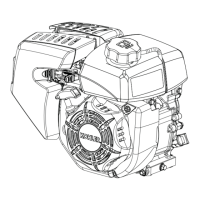
Injection pump, body, plunger and delivery valve
Components:
1 Collar
2
Barrel
3 Piston (or pumping element)
4 Right helix
5 Delay notch
6 Pump body
B Inlet hole
C Exhaust hole
Dimensions mm:
A = 7.00 (nominal diam.)
B = 2.00÷ 2.03
C = 1.50÷1.53