2.9 Technical data
2.9.1
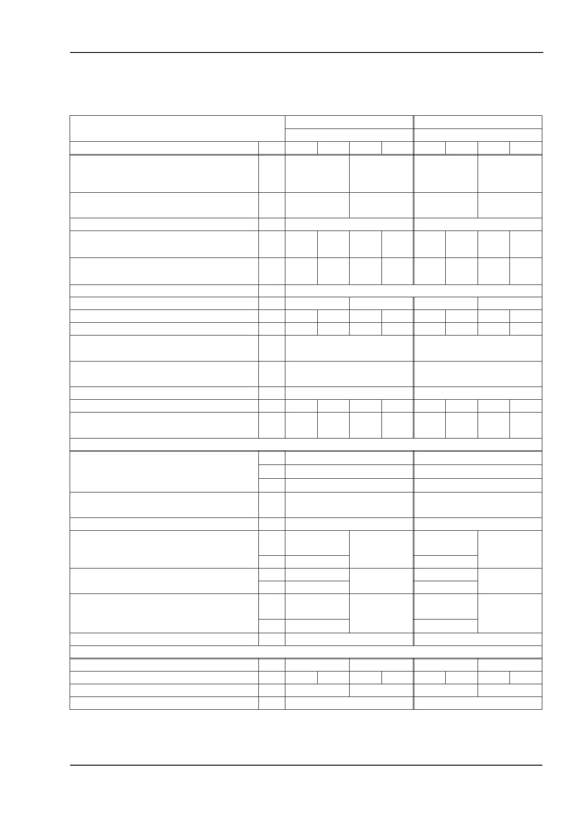
Rated data
max. 230VAC max. 400VAC
SERVOSTAR SERVOSTAR
Rated data DIM 403M 406M 403A 406A 443M 446M 403A 406A
Rated supply voltage V~
1 x 115V
-10%
to
3 x 230V
+10%
—
3 x 230V
-10%
to
3 x 400V
+10%
—
Max. installed load for S1 operation
(in a multi-axis system)
kVA 7 — 12 —
Rated DC Bus link voltage V= 160 - 310 310 - 560
Rated output current
(rms value, ± 3%, @ 8kHz)
Arms
36*36*36*36*
Peak output current
(max. ca. 5s, ± 3%, @ 8kHz)
Arms
9 12* 9 12* 9 12* 9 12*
Clock frequency of output stage kHz 8 (can be switched to 16, see page 12)
Overvoltage switch-off threshold V 450 — 750 —
maximum load inductance mH 75 40 75 40 75 40 75 40
minimum load inductance mH 12 7.5 12 7.5 12 7.5 12 7.5
Form factor of the output current (rated
conditions and min. load inductance)
— 1.01 1.01
Bandwidth of subordinate current
controller
kHz > 1.2 > 1.2
Residual voltage drop at rated current V < 5 < 5
Quiescent dissipation, output stage disabled W 12 15 12 15 12 15 12 15
Dissipation at rated current
(without regen dissipation)
W3560304035603040
Inputs/outputs
Analog input, 14-bit resolution V
±10 ±10
common-mode voltage max. V
±10 ±10
input resistance
kW
20 20
Digital control inputs
low 0...7 / high 12...36V,
7mA
low 0...7 / high 12...36V,
7mA
Digital control outputs, open emitter max. 30V, 10mA max. 30V, 10mA
BTB/RTO output, relay contacts
V
DC max. 30,
AC max 42
—
DC max. 30,
AC max 42
—
mA 500 500
Auxiliary supply, electrically isolated,
without holding brake, without fan
V 20...30
—
20...30
—
A 0.5 0.5
Auxiliary supply, electrically isolated,
with holding brake or fan
(check voltage drop !)
V
24
(-0% +15%)
—
24
(-0% +15%)
—
A 2.5 2.5
Max. output current for holding brake A 1,5 1,5
Mechanical
Weight kg 3 1.7 3 1.7
Height, without connectors mm 230 267* 230 267* 230 267* 230 267*
Width mm 100 50 100 50
Depth, without connectors mm 240 240
* with add-on ventilation, see page 66
SERVOSTAR
®
400 Installation Manual 15
Kollmorgen 07/05 Technical description
 Loading...


