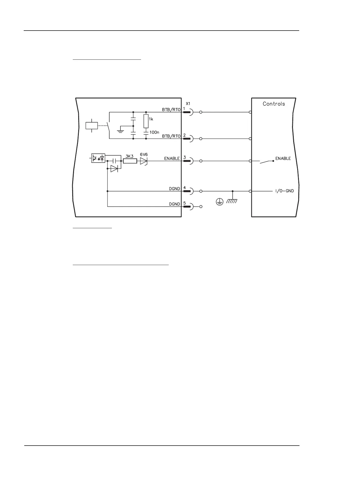
4.7.4 Digital control signals on the Master (X1)
Technical characteristics
— Ground reference is Digital-GND (DGND, terminal X1/4,5)
— The logic is dimensioned for +24V / 7mA (PLC-compatible)
— H-level from +12...36V / 7mA, L-level from 0...7V/0mA
BTB/RTO: Relay output, max. 30V DC or 42V AC, 0.5A
ENABLE input
The output stage of the servo amplifier is activated by the enable signal
(terminal X1/3, input 24V, active-high).
In the inhibited state (low signal) the motor which is attached does not have any torque.
Ready-to-operate contact BTB/RTO
Operational readiness (terminals X1/1 and X1/2 ) is signalled via a floating relay contact.
The contact is closed when all servo amplifiers in the system are ready for operation.
This signal is not influenced by the enable signal, the I²t- limit, or the regen threshold.
All faults cause the BTB/RTO contact to open and the output stage to switch off
A list of the error messages can be found on page 60.
44 SERVOSTAR
®
400 Installation Manual
Interfaces 07/05 Kollmorgen
SERVOSTAR 400
 Loading...


