2.10 Motor holding brake control
A motor holding brake (24V / max.1.5A) can be controlled directly by the servo amplifier.
This function does not ensure personnel safety!
The brake function must be enabled through the BRAKE parameter (on the screen page
for Motor): the setting is WITH.
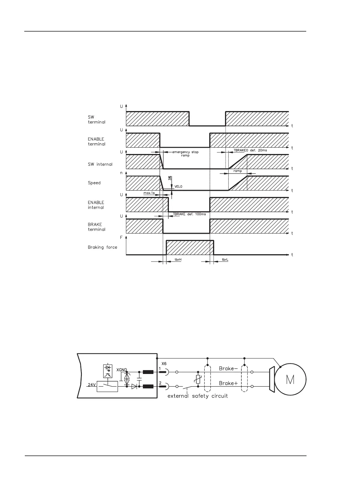
In the diagram below you can see the timing and functional relationships between the
ENABLE signal, speed setpoint, speed and braking force.
During the internal enable delay time of 100ms the speed setpoint of the servo amplifier is
internally driven down a 10ms ramp to 0V. The brake output is switched on when 3% of
the final speed is reached, at the latest after 1 second.
The rise (f
brH
) and fall (f
brL
) times of the holding brakes that are built into the motors vary
for the different types of motor (see motor manual).
A description of the interface can be found on page 38.
Personnel-safe operation of the holding brake requires an additional “make” contact in
the brake circuit and a spark suppressor device (e.g. a varistor) in the recommended
brake circuit:
18 SERVOSTAR
®
400 Installation Manual
Technical description 07/05 Kollmorgen
SERVOSTAR
 Loading...


