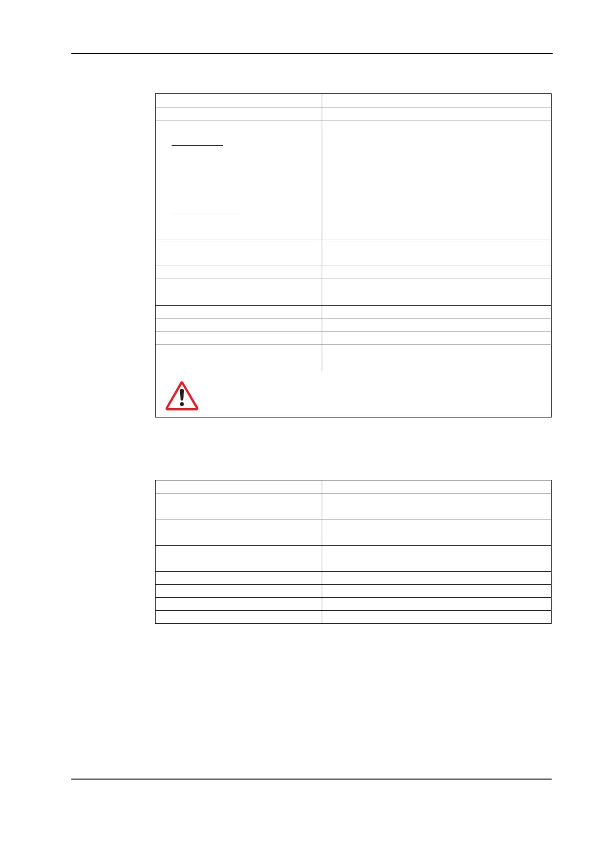
2.9.5 Permissible ambient conditions, ventilation, mounting position
Storage temp. /humidity/duration
ð p.67
Transport temperature/humidity
ð p.67
Supply voltage tolerances
main power
SERVOSTAR 40xM
SERVOSTAR 44xM
auxiliary supply
w/o brake and w/o fan
with brake or with fan
min 1x115V
-10%
AC / max 1x230V
+10%
, 50/60 Hz
min 3x115V
-10%
AC / max 3x230V
+10%
, 50/60 Hz
min 3x230V
-10%
AC / max 3x400V
+10%
, 50/60 Hz
20 VDC ... 30 VDC
24 VDC (-0% +15%)
Ambient temperature in operation
0...+45
o
C at rated conditions
+45...+55°C with power derating 2.5% / K
Humidity in operation
rel. humidity 85%, no condensation
Site altitude
up to 1000m amsl without restrictions
1000...2500m amsl with derating 1.5% / 100m
Pollution level Pollution level 2 as per EN 60204 / EN 50178
Enclosure rating IP 20
Mounting position
normally vertical ð p.25
Ventilation
SERVOSTAR4x3: free convection
SERVOSTAR4x6: add-on fan (ð p.66)
Make sure that there is adequate forced ventilation
within the closed control cabinet.
2.9.6 Conductor cross-sections
Following EN 60204-1, we recommend :
AC connection 1.5 mm², depending on the system fusing
Motor cables
1 mm², shielded, capacitance <150pF/m,
max. 25m
Resolver, motor thermostat
4x2x0.25 mm², twisted pairs, shielded, max.100m,
capacitance <120pF/m
Encoder, motor thermostat
7x2x0.25 mm², twisted pairs, shielded, max. 50m,
capacitance <120pF/m
Analog signals 0.25 mm² , twisted pairs, shielded
Control signals, BTB, DGND 0.5 mm²
Holding brake (motor) 0.75 mm², shielded, check voltage drop
+24 V / XGND max. 2.5 mm², check voltage drop
Technical requirements to cables ð p.33.
SERVOSTAR
®
400 Installation Manual 17
Kollmorgen 07/05 Technical description
 Loading...


