4.8 Encoder simulations
4.8.1
Incremental encoder output (X4)
The incremental-encoder interface is part of the package supplied. Select the encoder
function ROD (screen page “Encoder”, funktion ENCMODE). In the servo amplifier, the
position of the motor shaft is calculated from the cyclic-absolute signals of the resolver or
encoder.
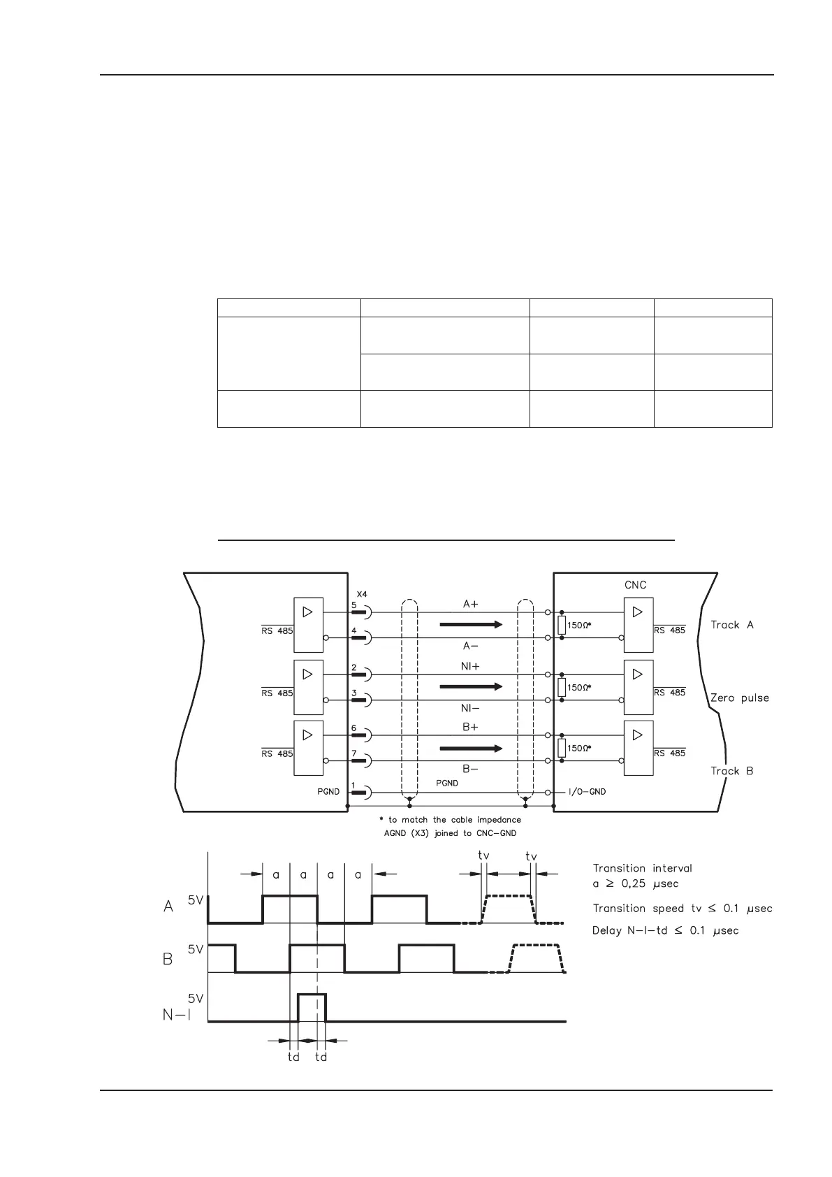
Incremental-encoder compatible pulses are generated from this information. Pulses are
output as two signals, A and B, with 90° phase difference and a zero pulse. The resolu
-
tion (lines before quadrature) can be changed with the RESOLUTION parameter:
Encoder function Feedback system Resolution Zero position
ROD (1)
Resolver 16...1024
one per revolution
(only if A=B=1)
EnDat / HIPERFACE
16...4096 and
8192...524288 (2n)
one per revolution
(only if A=B=1)
ROD interpolation (3)
Incremental encoders w/o
absolute data channel
4...128 TTL lines
per sine line
analog pass
through X1 to X5
You can also adjust and store the position of the zero pulse within one mechanical turn
(parameter NI-OFFSET).
The ground reference for the interface is PGND. PGND must always be connected to
the control ground. The max. admissible cable length is 10 m.
Connections and signal description for the incremental-encoder interface :
SERVOSTAR
®
400 Installation Manual 45
Kollmorgen 07/05 Interfaces
SERVOSTAR 400
 Loading...


