4.8.2 SSI output (X4)
The SSI interface (synchronous serial absolute-encoder emulation) is part of the package
supplied. Select encoder function ROD (“Encoder” screen page).
The servo amplifier calculates the motor shaft position from the cyclic-absolute signals of
the resolver or encoder. From this information a SSI date (after Stegmann patent specifi
-
cation DE 3445617C2) is provided.
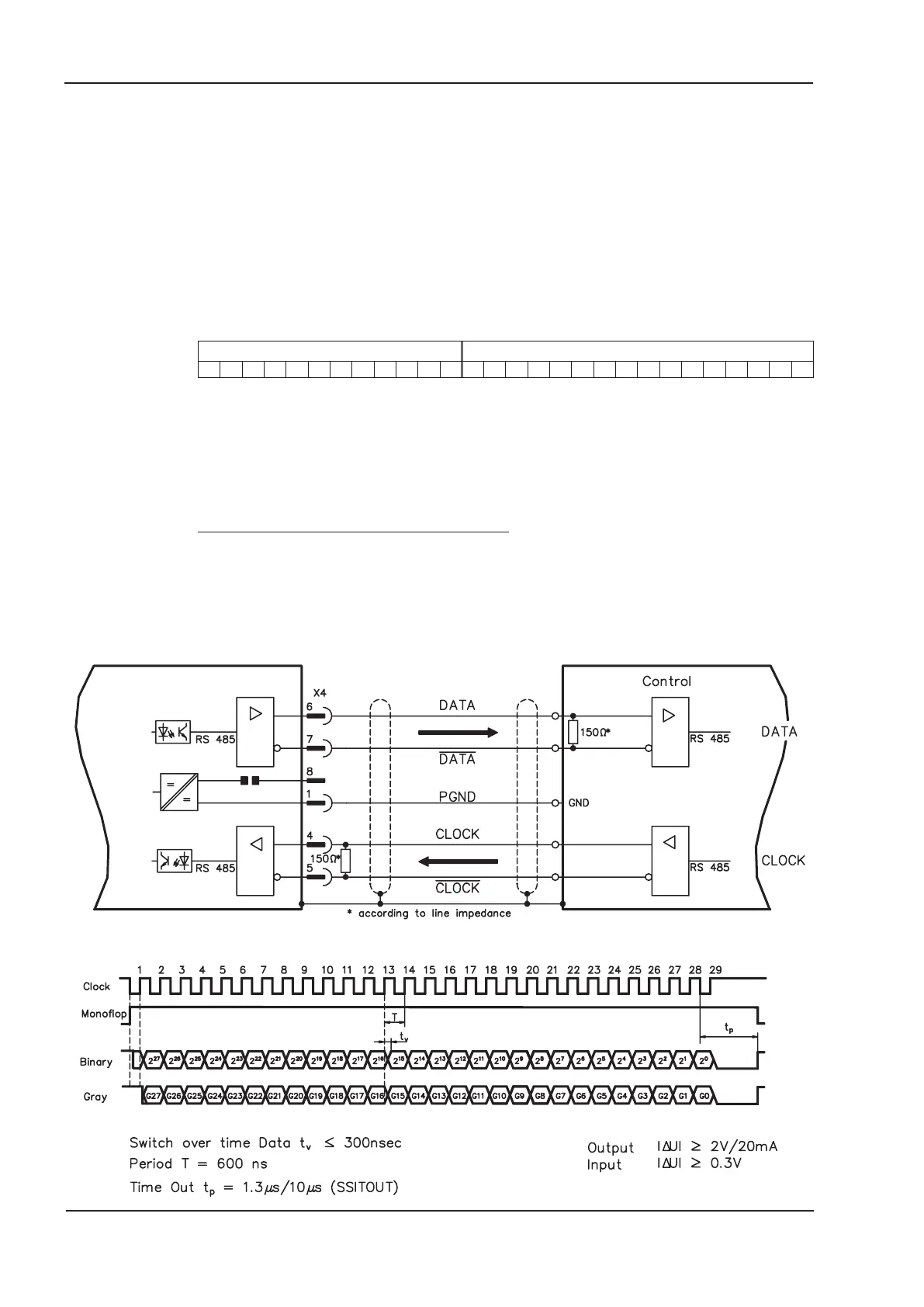
28 bits are transferred. The 12 leading data bits contains the number of revolutions. The
following max. 16 bits contain the resolution and are not variable.
The following table shows the allocation of the SSI date:
Revolution Resolution
111098765432101514131211109876543210
The signal sequence can be output in Gray code or in Binary (standard) code (parameter
SSI-CODE). The servo amplifier can be adjusted to the clock frequency of your SSI-eva
-
luation through the SSI-TIMEOUT parameter (1.3 µs or 10 µs).
The ground reference for the interface is PGND. PGND must always be connected to
the control ground.
Connection and signals for the SSI interface :
The count direction for the SSI interface is UP when the motor shaft is rotating clockwise
(looking at the end of the motor shaft).
46 SERVOSTAR
®
400 Installation Manual
Interfaces 07/05 Kollmorgen
SERVOSTAR 400
 Loading...


