Home
Kongsberg
Marine Equipment
EA440
Page 16 (Installation Preparations)
Kongsberg EA440 - Installation Preparations
92 pages
Manual
Save Page as PDF
To Next Page
To Next Page
To Previous Page
To Previous Page
Loading...
16
392616/B
Prepar
ations
T
opics
Installation
summary,
page
17
About
installation
dr
awings,
page
18
T
ools,
equipment
and
consumables
required
for
EA440
installation,
page
18
Where
to
install
the
tr
ansducer,
page
19
Acoustic
noise,
page
24
EA440
Installation
manual
15
17
Table of Contents
Main Page
Table of Contents
3
About this Manual
5
Ea440
6
System Diagram
7
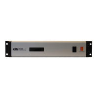
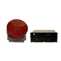
System Units
8
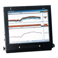
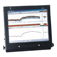
Operator Station Description
8
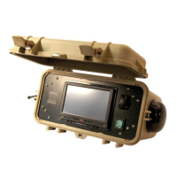
WBT Description
8
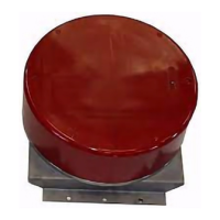
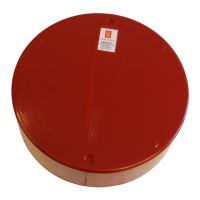
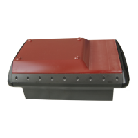
Single-Beam Transducers
9
Scope of Supply
10
Basic Items Provided with a Standard Delivery
10
Installation Requirements
12
Supply Power Requirements
12
Cables and Wiring Requirements
12
Compass Deviation Requirements
13
Noise Sources
13
Network Security
13
Support Information
15
Preparations
16
Installation Summary
17
About Installation Drawings
18
Tools, Equipment and Consumables Required for EA440 Installation
18
Where to Install the Transducer
19
Introduction to Transducer Location
19
Mount the Transducer Deep
19
Avoid Protruding Objects Near the Transducer
20
Keep the Transducer Far Away from the Propellers
21
Mount the Transducer at a Safe Distance from Bow Thruster(S)
21
Summary and General Recommendations
21
Acoustic Noise
24
Contributing Factors
24
Self Noise
26
Ambient Noise
28
Electrical Self Noise
28
Some Means to Reduce Acoustic Noise
29
Installing the Ea440 Hardware Units
31
Installing the WBT Using the Integrated Brackets
32
Installing the WBT in a 19" Cabinet
33
Installing a Commercial Computer
34
Mounting the WBT Cabinet
36
Mounting the Drawers in the WBT Cabinet
38
Designing, Manufacturing and Mounting the Steel Conduit
40
Installing the Transducer(S)
42
Installing the Transducer on a Blister or Drop Keel
43
Installing the Transducer on a Steel Hull
45
Cable Layout and Interconnections
47
Cable Plan
48
List of Cables
49
Installing the EA440 Cables
50
Connecting One or more Transducers to the WBT
50
Connecting Power and Ground to the WBT
54
Connecting the WBT and the Operator Station
55
Connecting a Synchronization Cable to the Operator Station Using an RS-232 Serial Interfaces
55
Cable Drawings and Specifications
57
Transducer
57
Auxiliary Connector for Synchronization
58
RS-232 Used as Synchronization Trigger (Input or Output)
59
Drawing File
60
388697 WBT Outline Dimensions
61
400930 WBT Cabinet Outline Dimensions
63
Technical Specifications
67
Performance Specifications
68
Interface Specifications
69
Weight and Outline Dimensions
72
Power Requirements
72
Environmental Specifications
73
Equipment Handling
74
Transporting Kongsberg Maritime Equipment
75
Lifting Units and Transportation Boxes
76
Inspection of Units and Transportation Boxes after Arrival
77
Specifications for Storage Prior to Installation or Use
78
Unpacking Instructions
79
Unpacking Standard Parts and Units
80
Unpacking Mechanical Units
81
Unpacking Electronic and Electromechanical Units
81
Unpacking Transducers
82
Specifications for Storage after Unpacking
84
Related product manuals
Kongsberg EA 400
220 pages
Kongsberg EA 600
172 pages
Kongsberg EK80
85 pages
Kongsberg EM 710
20 pages
Kongsberg EM 712
232 pages
Kongsberg EM 1002
394 pages
Kongsberg EM 3002
20 pages
Kongsberg EM 2040
20 pages
Kongsberg EM 2040C
124 pages
Kongsberg EM 2040P
130 pages
Kongsberg EM series
128 pages
Kongsberg EM - REV M
112 pages