500 SERIES INSTALLATION MANUALJULY 2016 PAGE 43
Step 10: Trim/Lift Control Module Installation (continued)
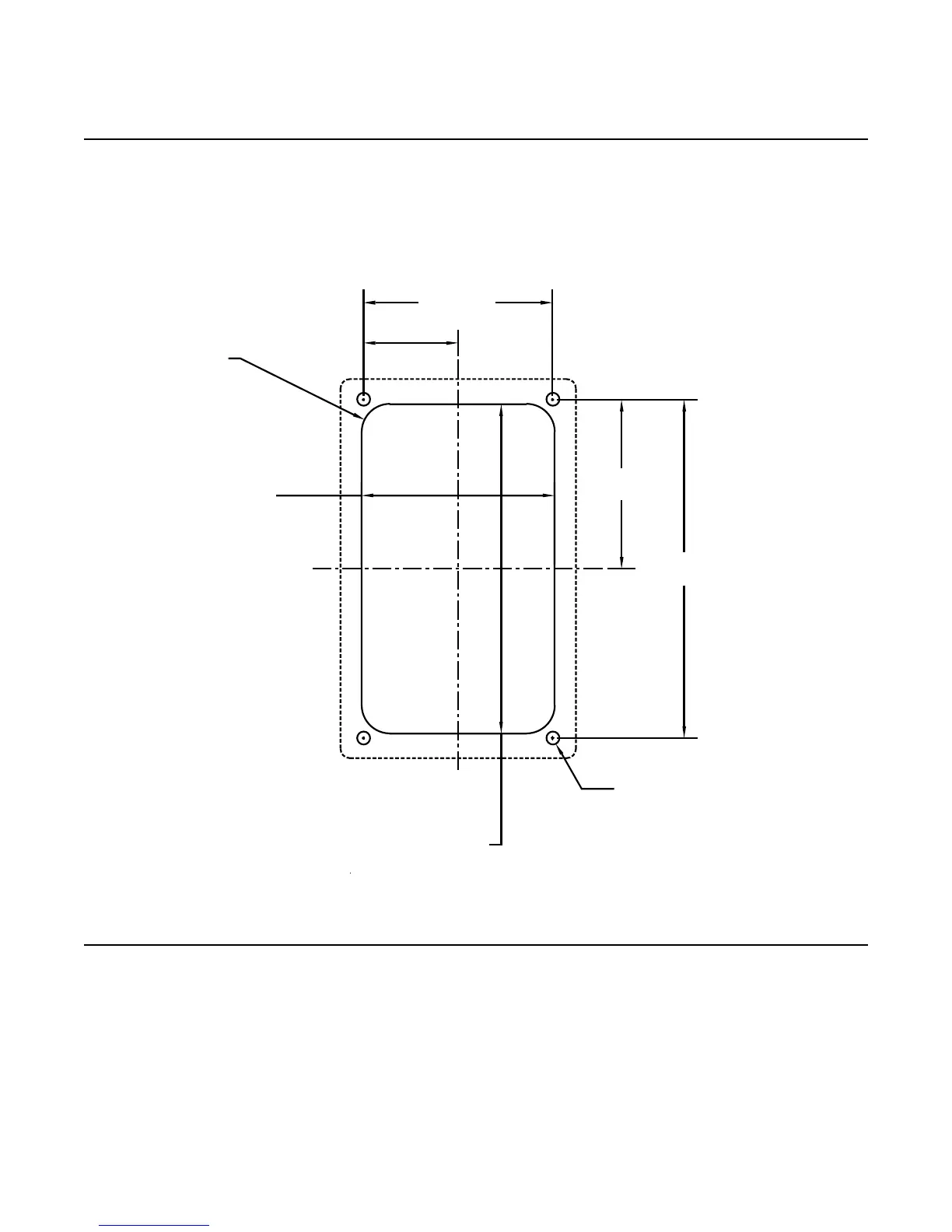
10.2 Layout the cutout area and mark the four (4) holes that
need to be drilled per the drawing below.
NOTE: Do not scale the drawing or use it as a template.
10.3 Use a reciprocating saw to cut out the area laid out in
the previous step. Drill the four (4) holes laid out in the
previous step.
NOTE: Touch up and remove burs from the cutout area
with a le.
4x R
3
/
8
(R9.5mm)
4x 0
11
/
64
(04.5mm)
2.563
(65.1mm)
4.375
(111.1mm)
(63.8mm)
2.247
(57.1mm)
4.494
(114.1mm)
1.255
(31.9mm)