500 SERIES INSTALLATION MANUAL JULY 2016PAGE 44
FIGURE 10C
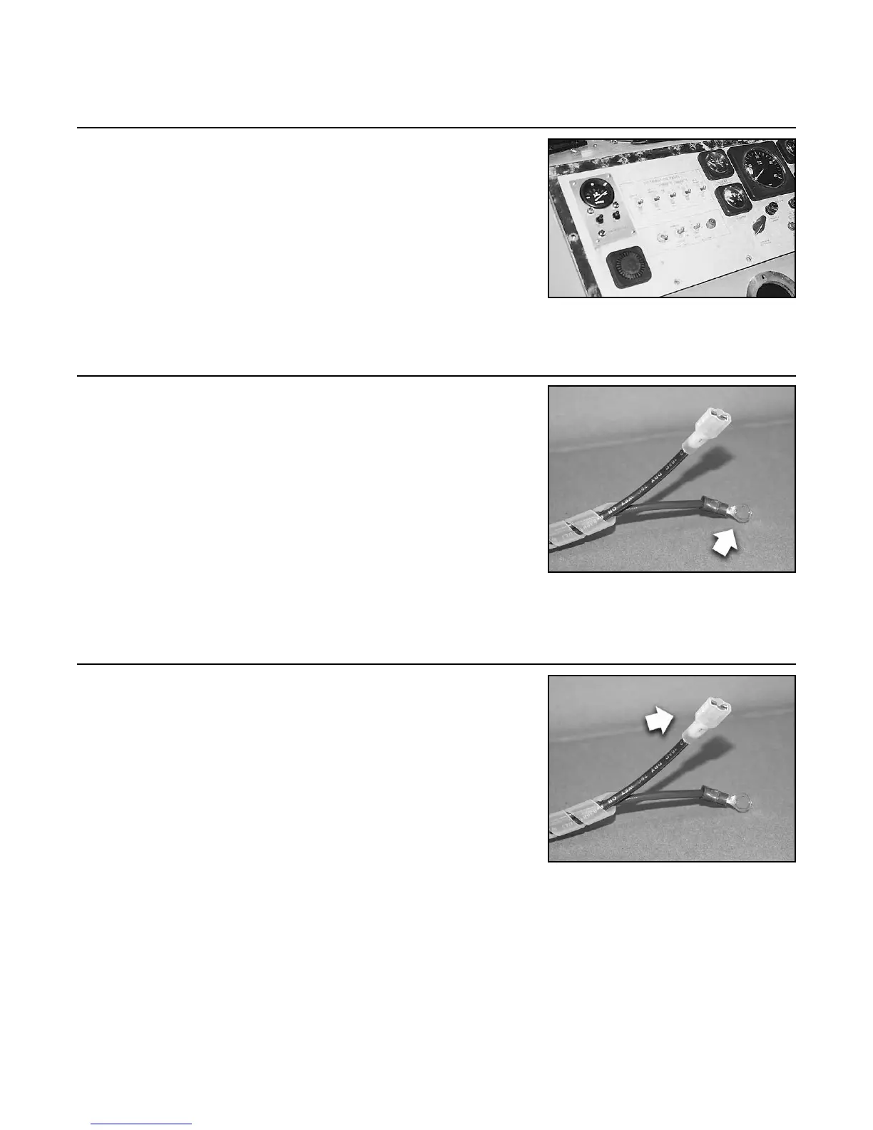
10.4 Mount the module in the cutout area using the hardware
provided.
NOTE: If access under the panel is limited, the module
may need to be wired before mounting.
10.5 Connect the purple wire to a +12 VDC or +24 VDC source
(whichever is the operating voltage of the vessel) that is
powered when the ignition key is in the “on” position.
NOTE: Refer to the Trim System Electrical Drawings
(Figure C and Figure D on pages 22 and 23 in this
manual) for further documentation on this and proceeding
instructions.
NOTE: Battery or batteries must be disconnected while
all electrical connections are being made.
10.6 Connect the blue wire to the positive side of the instrument
panel illumination circuit.
Step 10: Trim/Lift Control Module Installation (continued)
FIGURE 10D
FIGURE 10E