500 SERIES INSTALLATION MANUALJULY 2016 PAGE 53
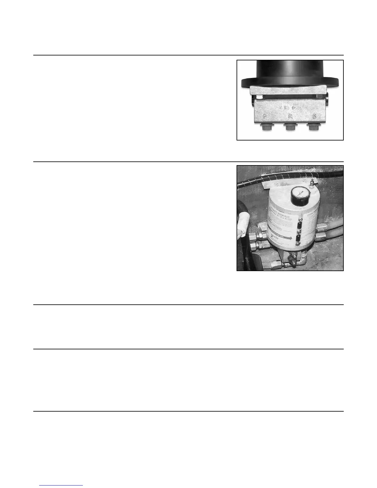
13.11 Attach the other three (3) hydraulic steering lines to the
helm assembly, observing port, starboard and reservalve
identication.
NOTE: Please refer to the 30-462R routing diagram
(Figure H on page 54 in this manual) for assistance and
further explanation.
13.12 Attach all ve (5) lines to the reservalve.
NOTE: Please refer to the 30-462R routing diagram
(Figure H on page 54 in this manual) for assistance and
further explanation.
13.13 Fill helm assembly or reservoir valve with the appropriate
uid.
13.14 Bleed system per manufacturer’s specications.
NOTE: Additional uid may need to be added during the
bleeding process.
13.15 Check system for leaks.
Step 13: Manual Hydraulic Steering Installation (continued)
FIGURE 13K
FIGURE 13L