22
2
05 / 2018
© 2018 KOSTAL Solar Electric GmbH
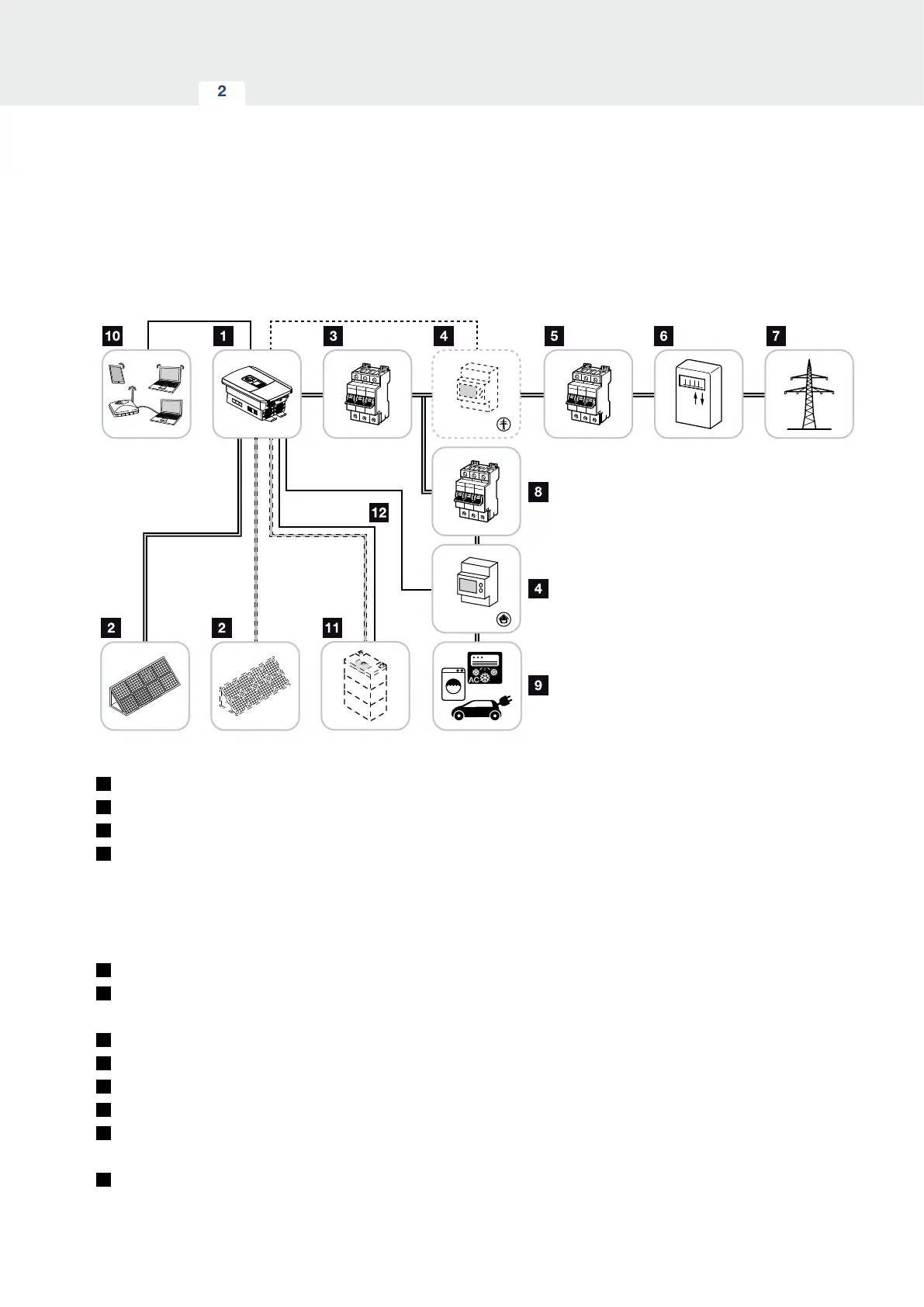
Device and system description
Inverter with 2 PV inputs and
1 DC battery connection
LAN
CAN / RS485
BMS
Modbus RTU
Modbus RTU
Position 1
Position 2
Fig. 8: Photovoltaic system with PV and battery connection
1
Inverter
2
PV generators (number depends on the type)
3
Line circuit breaker for inverter
4
Digital energy meter ( Modbus RTU)
home consumption (position 1) or grid connection
(position 2). Position 1 should be the preferred
option because this provides more accurate home
consumption measuring values.
5
Main fuse building
6
Procurement and feed meter or smart meter
(not in all countries)
7
Public grid
8
Line circuit breaker for energy consumers
9
Energy consumers
10
Communication link for inverter
11
Connection for battery system (available as option
after activation)
12
Communication connection for battery management
system (BMS) via CAN or RS485
 Loading...