50
3
© 2018 KOSTAL Solar Electric GmbH
Installation
1
1
1
1
1
4
7
6
2
3
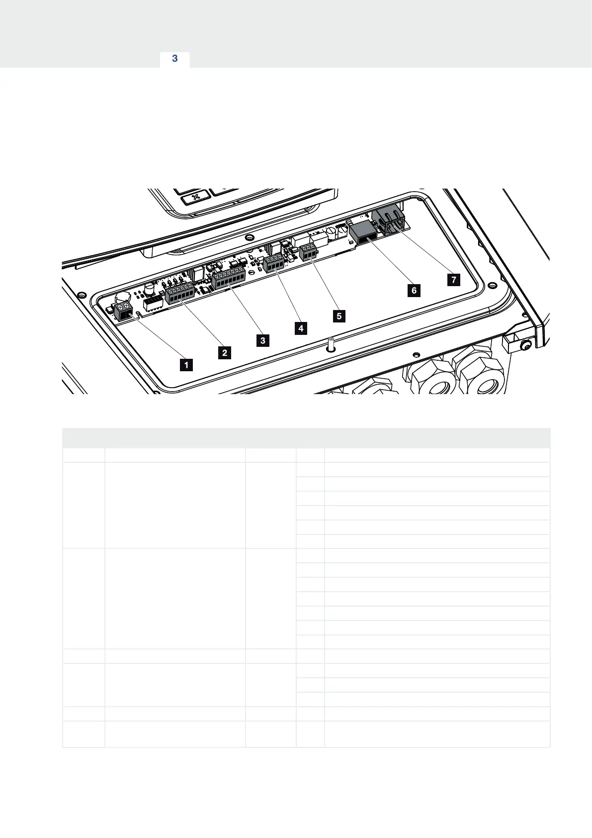
Fig. 25: Smart Communication Board– interfaces
Item Designation terminal Pin Explanation
1 Terminal for self-consumption X461 1 - 2 Contact (NO switch) for self-consumption control
2 Terminal for digital connection for
ripple control receiver or control
box
X401 1 VDD (+12 to 14 V supply voltage)
2 Input 1
3 Input 2
4 Input 3
5 Input 4
6 GND (0 V ground)
3 Terminal for communication with
battery via RS485 or CAN
X601 1 VDD (+12 to 14 V supply voltage)
2 CANopen High interface (data +)
3 CANopen Low interface (data -)
4 RS485 interface B (data -)
5 RS485 interface A (data +)
6 GND (0 V ground)
7 not used
4 Not used (terminal X602) X602 1 - 4 -
5 Terminal for energy meter
( Modbus RTU)
X452 1 Interface A (data +) RS485/ Modbus RTU
2 Interface B (data -) RS485/ Modbus RTU
3 GND
6 USB 2.0 interface X171 1 USB 2.0 max. 500 mA (currently only for service)
7 Ethernet connection (RJ45) X206 1 RJ45 max. 100 Mbit (LAN connection for linking to a
router, for example)
3.5 Overview of Smart Communication Board (SCB)