45
3
© 2018 KOSTAL Solar Electric GmbH
Installation
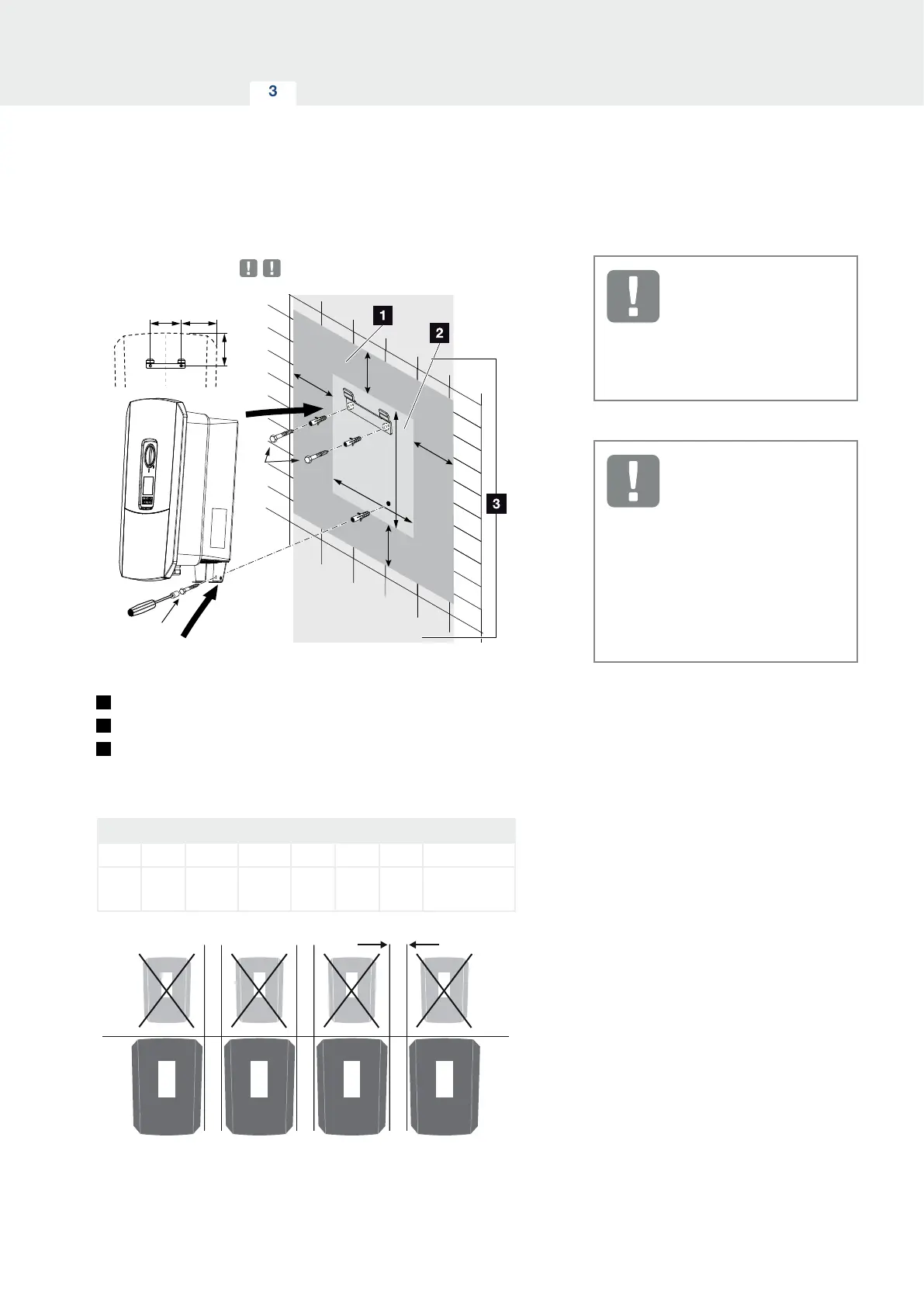
Wall mounting
B
B
A
A
C
D
H
H
G
FE
1.
2.
Fig. 17: Wall mounting with wall mount
1
Clearance
2
Outer dimensions of the inverter
3
Inverters may not be installed in this area
You can find the distances for wall mounting in the fol-
lowing table:
Dimensions in mm (inch)
A B C D E F G H
100
(3.9)
200
(7.9)
405
(15.94)
563
(22.17)
122
(4.8)
141
(5.55)
128
(5.04)
min. DIN571
A2-70 6x45
Fig. 18: Wall mounting of several inverters
IMPORTANT
INFORMATION
Be absolutely sure to maintain the
clearance around the inverter in or-
der that the inverter remains cool.
IMPORTANT
INFORMATION
To install the inverter, use the
wall mount with 2 retaining bolts
(included in scope of delivery) suit-
able for the existing base.
Fix the inverter to the wall at the
bottom using a 3rd bolt (included in
scope of delivery).