63
3
© 2018 KOSTAL Solar Electric GmbH
Installation
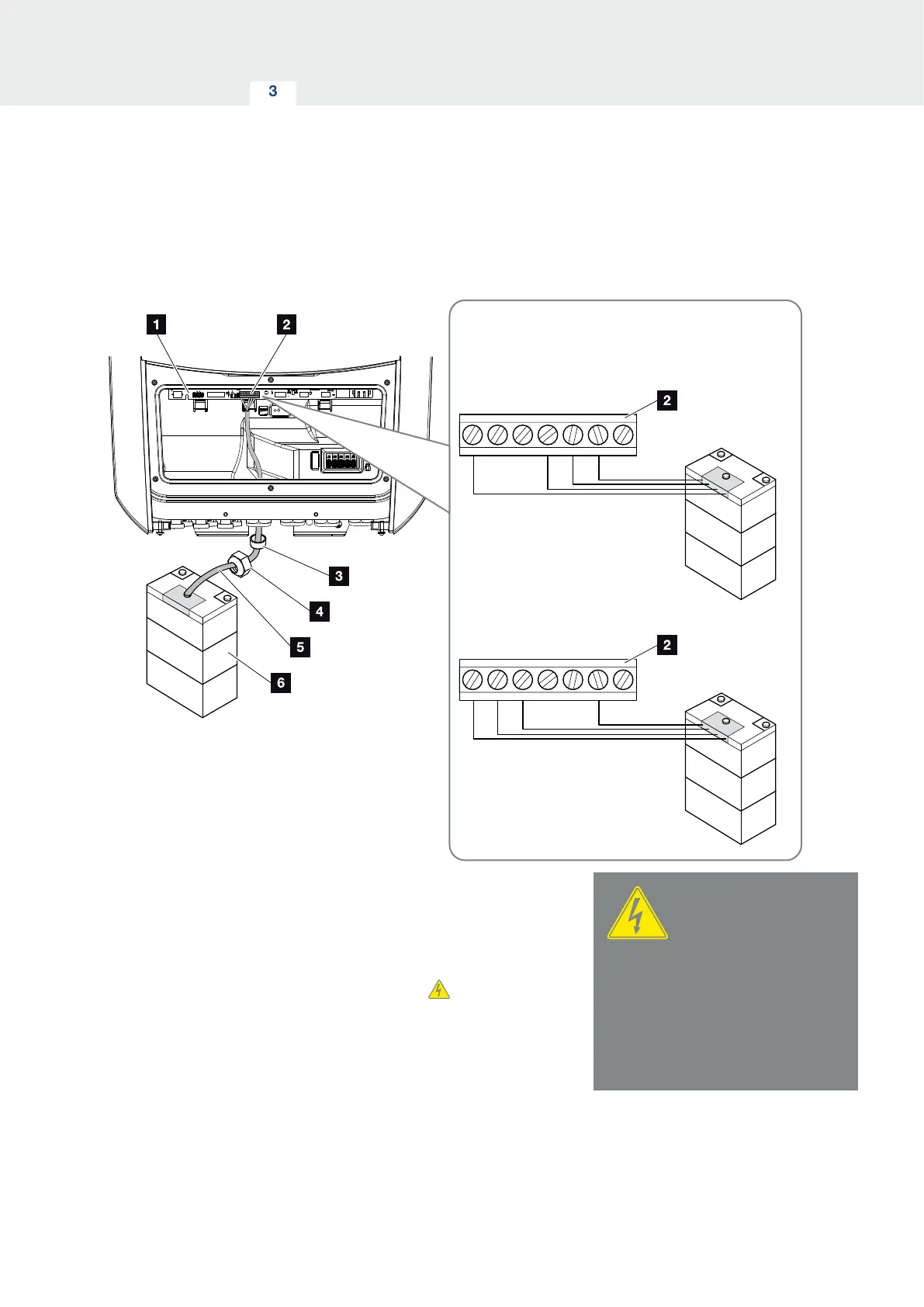
Battery communication connection
L1 L2 L3 N
BMS
BMS
BMS
GND 0V
CAN
CANopen low
CANopen high
VDD +12-14V
GND 0V
RS485
RS485 B
RS485 A
VDD +12-14V
X601
X601
Fig. 35: Battery communication connection via RS485 or CAN
1. The communication cable may only be connected to
the inverter if the terminal compartment of the
inverter and battery storage are voltage-free.
De-energise inverter and battery storage.
DANGER
RISK OF DEATH DUE TO ELECTRI-
CAL SHOCK AND DISCHARGE!
De-energise inverter and battery
storage. Please also observe the
instructions in the operating man-
ual provided by the battery manu-
facturer.
 Loading...