Part 2: Overview of display values and settings Expert area
33
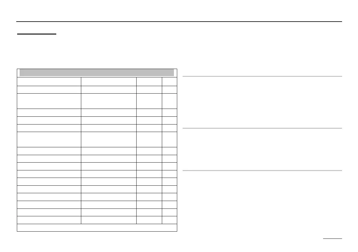
Expert area
These settings can only be changed if the code no. is en-
tered (see page 16).
E If these values are set incorrectly, they may cause
malfunctions or damage to the system.
Installation
Designation Value range Default IV
CODE-NO 0000 - 9999 Entry
CODE-NO
(Adjustment)
0000 - 9999 0000
BUS-ID HS ----, 01 - 08 ----
BUS ID 1 (- - - - ,00), 01 - 15 01
BUS ID 2 (- - - -), 02 - 15 02
BUS TERMIN 00, 01 (OFF/ON) 01
00
EBUS SUPPLY 00,01 (OFF / ON) 01 =
AF SUPPLY 00,01 01 =
TIME MASTER 00, 01 00 =
DYN UPWARD *)
20 – 500 K 100 K
DYN DOWNWARD *)
20 – 500 K 100 K
RESET TIME *)
5 - 500 50
MAX T-HS 30 °C – 110 °C 85 °C
MIN T-HS 10 °C – 80 °C 40 °C
T-WARM UP 10 °C – 85 °C 35 °C
MIN-DELIMI 00, 01, 02 00
See following pages for continuation
*) only for HS via eBUS
1) Controller .0324-P and .0634-P = 67 °C
2) Controller .0324-P and .0634-P = 62 °C
3) Controller .0324-P and .0634-P = 01
CODE-NO
Entering the code number (see page 16) allows all of the
expert settings to be modified => including the code num-
ber itself (first parameter)
(Ç on right => CODE-NO 0000
Ä=> Ç 1st digit
Ä=> Ç
2nd digit
Ä=> Ç 3rd digit Ä=> Ç 4th digit
Ä=> Ç)
BUS-ID HS (- - - -) (not an option in all models)
The controller will be used as cascade with setting
"01 - 08". Settings > 08 can only be supported when cas-
cading of cascades with corresponding cascade manag-
ers.
BUS ID1 / 2 (heating circuit number)
The heating circuits are sequentially numbered starting
with "01". heating circuit numbers must not be assigned
twice. For replacement controllers, please enter exactly the
same heating circuit numbers as the replaced controller.